


Description
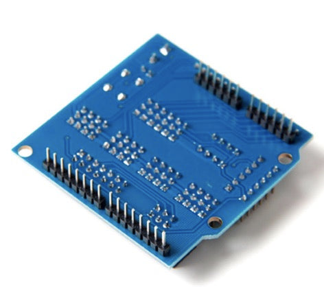
This is an IO expansion shield designed for Arduino Uno (or Mega) that allows you to connect to many sensor modules and servo motors easily. You can easily build various projects using this shield, save up the time from hassles due to messy wiring, insufficient power pin available (Uno and Mega has only one 5V pins and three GND pins available without expansion).
The Sensor Shield V5.0 fits Uno, Mega 2560 and similar form-factor Arduino boards and provides a convenient way to interface to sensors and other peripherals such as servo motors. It expand all the pins of an Arduino Nano for easier connection to external devices. The expanded pins using 1?3 header pins are arranged in SVG configuration for all pins so it is directly compatible with servo pin configuration.
Features
- IO expansion for all digital, analog pins
- Pin expansion for I2C and UART interfaces
- Does not have 3.3V power output
- Expanded pins arranged in SVG configurations
- Input voltage : 5V
- Can be fit onto Arduino Mega
Wiring

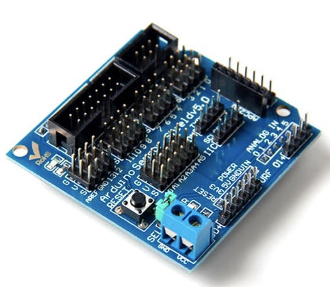
KEY FEATURES OF SENSOR SHIELD V5.0:
This shield brings out the standard Arduino I/O pins to headers along with dedicated ground and power pins per I/O to facilitate connecting sensors other devices.
The shield also has a number of dedicated connectors that are defined for specific purposes as outlined below, but they can also be considered as general purpose connection points.
An auxiliary power connector allows separate power to be supplied to the power pins associated with the D0-D13 pins which is handy for driving servo motors.
A remote reset switch is located on the shield for easy access. It also brings the on-board pin-13 ‘L’ LED up to the shield for easy visibility.
Power System
One of the benefits of this shield is that it brings each of the standard Arduino I/O pins out to 3-pin headers along with a dedicated Ground and Vcc pin.
The VCC pins associated with A0-A5 as well as the misc I/O connectors are all hardwired to the Arduino 5V power. Sensors generally need as clean of power as possible, so keeping these on the Arduino 5V makes sense.
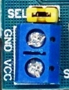
The VCC pins associated with D0-D13 are controlled by the SEL jumper.
SEL jumper installed = The Arduino 5V power is connected to these pins as well. This mode facilitates using digital sensors and other low power I/O.
SEL jumper removed = The Arduino 5V power is removed and the power for the pins must be supplied by a separate power supply connected to the 2-pos screw terminal. This is commonly used when servo motors are being driven so that they can be powered from a separate power supply since they exceed the current capability of the built-in 5V and the servo motors create too much electrical noise back into the Arduino electrical system.
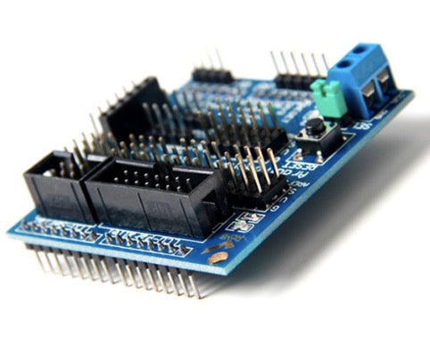
2-Pos Screw Terminal
-
GND = Ground for separate power supply
- VCC = Positive voltage from separate power supply. Typically 5-6V for servos, but can be other voltage as required by the system.
Note: With the SEL jumper installed, there must not be external power applied to the 2-pos screw terminal or damage may result since it will short the external and on-board power systems together.
Digital I/O Headers
This group of headers simply brings out the D0 thru D13 Digital I/O lines and couples them with a dedicated ground and VCC pin. The SEL jumper determines the power that is supplied to the VCC pins as noted above.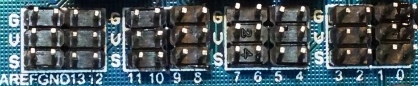
3 x 16 Header
- G = Ground
- V = Vcc (Source determined by SEL jumper)
- 0 – 13 = Digital I/O lines D0 thru D13
Also note that AREF is brought on this line of headers. AREF is the analog reference voltage for the Arduino ADC.
Analog I/O Headers
This group of headers simply brings out the A0 thru A5 Analog I/O lines and couples them with a dedicated ground and VCC pin. The analog inputs can also be used as additional digital I/O lines.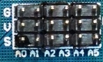
3 x 6 Header
- G = Ground
- V = 5V
- A0-A5 = Analog inputs A0 thru A5
SD (SD Card Interface)
This header provides the three SPI data lines on D11-D13 as well as D10 for an SD Card Select line and power and ground. Originally designed to interface to SD memory cards but can be used to connect to any SPI device.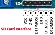
1×6 Header
- VCC = 5V
- GND = Ground
- D11 = SPI MOSI
- D10 = For use as SD card select
- D12 = SPI MISO
- D13 = SPI SCK
URF01 (Ultrasonic / Ping Interface)
This header provides a couple of analog lines which can also be used as digital I/O along with power and ground. Originally designed for use with some analog output ultrasonic devices, but can also be used with HC-SRF04 and similar digital devices.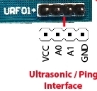
1×4 Header
- VCC = 5V
- A0 = Analog input 0. Can also be used as digital I/O
- A1 = Analog input 1. Can also be used as digital I/O
- GND = Ground
Bluetooth
This header provides the RX/TX serial comm lines used to interface to Bluetooth devices. It also provides both 5V and 3.3V power since some Bluetooth operates at 3.3V levels. This connector can be used to connect to any serial device.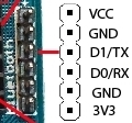
1×6 Header
- VCC = 5V
- GND = Ground
- D1 = Serial Port RX line
- D0 = Serial Port TX line
- GND = Ground
- 3V3 = Arduino 3.3V power
APC220 (Wireless Interface)
This female header provides the RX/TX serial comm lines used to interface to APC220 wireless devices. It also provides 5V and ground This connector can be used to connect to any serial device.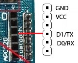
1×6 Female Header
- GND = Ground
- VCC = 5V
- N/C
- D1 = Serial Port RX line
- D0 = Serial Port TX line
- N/C
IIC (I2C interface)
This header simply brings out the A4 and A5 lines which also carry I2C signals along with 5V and ground.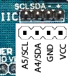
1×4 Header
- SCL = A5 / I2C SCL
- SDA = A4 / I2C SDA
- ‘-‘ = Ground
- ‘+’ = 5V
COM (Serial Communications Interface)
This header simply brings out the serial communication TX and RX lines along with 5V and ground.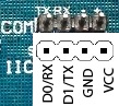
1×4 Header
- TX = D1 / Serial TX line
- RX = D0 / Serial RX line
- ‘-‘ = Ground
- ‘+’ = 5V
LCD Serial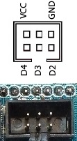
This shrouded header provides D2-D4 along with power and ground for connecting to a serial LCD display.
2×3 Header
- VCC = 5V
- GND = Ground
- D2 – D4 = Digital I/O pins
LCD Parallel
This shrouded header provides D2-D13 along with power and ground for connecting to a parallel interfaced LCD display.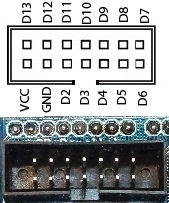
2×7 Header
- VCC = 5V
- GND = Ground
- D2 – D13 = Digital I/O pins
OUR EVALUATION RESULTS:
Build quality on these assemblies is reasonable. Headers are not always fully seated and completely straight but we inspect each one to make sure they are reasonably aligned.
We have found some modules on the market that the ground pins on the LCD parallel interface and the SD card interface are not actually connected to ground due to an apparent PCB layout issue. We inspect for this and correct these if found. If you are using a shield from another source and have issues with those interfaces, you should double-check the ground connections and if missing you will need to jumper these pins to ground.