


Description:
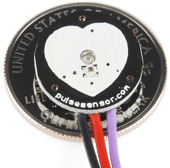
The Heart Rate Pulse Sensor Module with Soldered Wire is a versatile and reliable device for accurate heart rate monitoring. This compact module utilizes advanced optical sensing technology to provide real-time heart rate data for a variety of applications. With its plug-and-play compatibility, it can be easily integrated into Arduino and other microcontroller projects without the need for complex wiring or soldering. The pre-soldered wires ensure a secure connection, making it convenient for users of all levels of expertise. The module features an integrated amplifying and noise elimination circuit, enhancing the accuracy of heart rate measurements by minimizing interference. Its low power consumption makes it suitable for battery-powered devices, maximizing energy efficiency. The user-friendly design includes a heart logo where the finger is placed for detection, along with a green LED for optimal signal detection and an ambient light photosensor for automatic brightness adjustment. With a reverse protection diode, the module offers added safety in case of accidental reverse polarity. Whether you're developing wearable devices, fitness trackers, or health monitoring systems, this module provides a compact, reliable, and efficient solution for precise heart rate monitoring.
Features
- Includes Kit accessories for high-quality sensor readings
- Designed for Plug and Play
- Small size and embeddable into wearables
- It works with any MCU with an ADC
- Works with 3 Volts or 5 Volts
- Well-documented Arduino library
Package Included:
- 1 x Pulse sensor Heart Rate Sensor PulseSensor module
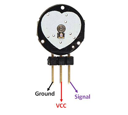
Pin Configuration
|
Pin Number |
Pin Name |
Wire Colour |
Description |
|
1 |
Ground |
Black |
Connected to the ground of the system |
|
2 |
Vcc |
Red |
Connect to +5V or +3.3V supply voltage |
|
3 |
Signal |
Purple |
Pulsating output signal. |
How Pulse Sensor Work
The working of the pulse/heartbeat sensor is very simple. The sensor has two sides; on one side, the LED is placed along with an ambient light sensor, and on the other side, we have some circuitry. This circuitry is responsible for the amplification and noise cancellation work. The LED on the front side of the sensor is placed over a vein in our human body. This can either be your fingertip or your ear tip, but it should be placed directly on top of a vein.
Now the LED emits light, which will fall on the vein. The veins will have blood flow inside them only when the heart is pumping, so if we monitor the flow of blood, we can monitor the heartbeats as well. If the flow of blood is detected, then the ambient light sensor will pick up more light since it will be reflected by the blood. This minor change in received light is analyzed over time to determine our heartbeats.
Applications
- Sleep Tracking
- Anxiety monitoring
- Remote patient monitoring/alarm system
- Health bands
- Advanced gaming consoles
Wiring a Pulse Sensor to an Arduino
Connecting the Pulse Sensor to an Arduino is a breeze. You only need to connect three wires: two for power and one for reading the sensor value.
The module can be supplied with either 3.3V or 5V. Positive voltage is connected to ‘+,’ while ground is connected to ‘-.’ The third ‘S’ wire is the analog signal output from the sensor, which will be connected to the Arduino’s A0 analog input.
The following is the wiring diagram for the Pulse Sensor experiments:

Library Installation
To run the following sketches, you must first install the ‘PulseSensor Playground’ library.
To install the library, navigate to Sketch > Include Library > Manage Libraries… Wait for the Library Manager to download the libraries index and update the list of installed libraries.

Filter your search by entering ‘pulsesensor’.There should only be a single entry. Click on that and then choose Install.

Pulse Sensor Example Sketches
The Pulse Sensor library includes several example sketches. We’ll go over a few of them here, but you can also experiment with the others.
To access the example sketches, navigate to File > Examples > PulseSensor Playground.
You will see a selection of example sketches. You can choose any of them to load the sketch into your IDE. Let’s start off with the GettingStartedProject.

Arduino Example 1 – Blink with the Heartbeat
Load the GettingStartedProject sketch from the example sketches into your Arduino IDE. This is a basic Arduino sketch. Upload the code to your Arduino and clip the sensor to your earlobe or fingertip. You should see the Arduino’s onboard LED blink in time with your heartbeat!
int const PULSE_SENSOR_PIN = 0;   // 'S' Signal pin connected to A0

int Signal;                // Store incoming ADC data. Value can range from 0-1024
int Threshold = 550;       // Determine which Signal to "count as a beat" and which to ignore.

void setup() {
	pinMode(LED_BUILTIN,OUTPUT);  // Built-in LED will blink to your heartbeat
	Serial.begin(9600);           // Set comm speed for serial plotter window
}

void loop() {

	Signal = analogRead(PULSE_SENSOR_PIN); // Read the sensor value

	Serial.println(Signal);                // Send the signal value to serial plotter

	if(Signal > Threshold){                // If the signal is above threshold, turn on the LED
		digitalWrite(LED_BUILTIN,HIGH);
	} else {
		digitalWrite(LED_BUILTIN,LOW);     // Else turn off the LED
	}
	delay(10);
}
Code Explanation
The sketch is extremely simple. It starts with defining the pin used to connect the Pulse Sensor. Two variables are also defined; the Signal variable holds the incoming ADC data and the Threshold variable determines which signal to “count as a beat” and which signal to disregard.
int const PULSE_SENSOR_PIN = 0;

int Signal;
int Threshold = 550;
In the setup, we configure the onboard LED pin (pin 13) to act as an output and set up the serial monitor.
void setup() {
	pinMode(LED_BUILTIN,OUTPUT);
	Serial.begin(9600);
}
In the loop, we read the analog signal from the Pulse Sensor and activate the onboard LED when the signal exceeds a threshold value.
void loop() {
	Signal = analogRead(PULSE_SENSOR_PIN); // Read the sensor value

	if(Signal > Threshold){                // If the signal is above threshold, turn on the LED
		digitalWrite(LED_BUILTIN,HIGH);
	} else {
		digitalWrite(LED_BUILTIN,LOW);     // Else turn off the LED
	}
	delay(10);
}