


Description
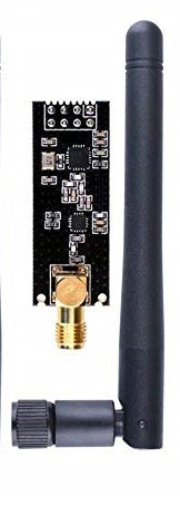
NRF24L01P + PA + LNA wireless module integration is extremely high, the size is 41mm x 15.5mm to make conveniently embedded.
Specifications
- Operating Frequency: 2400MHz ~ 2524MHz
- Modulation: GMSK
- Transmit power: more than +20 dbm
- Receiver sensitivity:-95dbm
- Operating voltage: 2.7V ~ 3.6V
- Max Emission current: 115mA
- Max Receive current: 45mA
- Operating temperature: -45 degrees to +85 degrees
- Storage temperature: -45 degrees to +125 degrees
- Gain Of PA: 20 dB
- Gain Of LNA: 10 dB
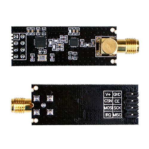
Pinout

GND is the ground pin. It has a square marking to distinguish it from the other pins.
VCC supplies power to the module. It can range from 1.9 to 3.9 volts. You can connect it to your Arduino’s 3.3V output. Please keep in mind that connecting this to the 5V pin will most likely damage your nRF24L01+ module.
CE (Chip Enable) is an active-high pin. When enabled, the nRF24L01 will either transmit or receive, depending on the mode.
CSN (Chip Select Not) is an active-low pin that is typically held HIGH. When this pin goes low, the nRF24L01 begins listening for data on its SPI port and processes it accordingly.
SCK (Serial Clock) accepts clock pulses from the SPI bus master.
MOSI (Master Out Slave In) is the SPI input for the nRF24L01.
MISO (Master In Slave Out) is the SPI output of the nRF24L01.
IRQ is an interrupt pin that can notify the master when there is new data to process.
Wiring
To begin, connect the module’s VCC pin to Arduino’s 3.3V and the GND pin to ground. CSN and CE pins can be connected to any digital pin on an Arduino; in our case, they are connected to digital pins #8 and #9.
Let’s wire up the SPI pins. Note that each Arduino board has a unique set of SPI pins that must be connected accordingly. For Arduino boards such as the UNO/Nano V3.0, these pins are digital 13 (SCK), 12 (MISO), 11 (MOSI) and 10 (SS).
If you’re using a different Arduino board, check the official documentation for SPI pin locations before proceeding.
The following table lists the pin connections:
| nRF24L01+ module | Arduino | |
| GND | GND | |
| VCC | 3.3V | |
| CE | 9 | |
| CSN | 8 | |
| SCK | 13 | |
| MOSI | 11 | |
| MISO | 12 |

Remember, you need to make two such circuits. One will act as a transmitter and the other as a receiver. Both have the same wiring.
Once you have connected everything, you are ready to go!
Library Installation
There are many libraries available for the nRF24L01+ module, but one of the most popular is RF24. This library has been around for a long time. It’s simple to use for beginners while still providing a lot for advanced users. We will use this library in our examples.
To install the library, navigate to Sketch > Include Library > Manage Libraries… Wait for the Library Manager to download the library index and update the list of installed libraries.
Filter your search by entering ‘rf24‘. Look for the library by TmRh20. Click on that entry and then choose Install.
Code – For Transmitter
The examples below demonstrate how to set up a simple one-way link between a transmitter and a receiver. The transmitter simply sends a traditional ‘Hello World’ message to the receiver, which displays it in the Serial Monitor window.
This is the code we’ll use for our transmitter.
//Include Libraries
#include <SPI.h>
#include <nRF24L01.h>
#include <RF24.h>

//create an RF24 object
RF24 radio(9, 8);  // CE, CSN

//address through which two modules communicate.
const byte address[6] = "00001";

void setup()
{
  radio.begin();

  //set the address
  radio.openWritingPipe(address);

  //Set module as transmitter
  radio.stopListening();
}
void loop()
{
  //Send message to receiver
  const char text[] = "Hello World";
  radio.write(&text, sizeof(text));

  delay(1000);
}
Code Explanation
The sketch begins by including the necessary libraries. The SPI.h library handles SPI communication, while the nRF24L01.h and RF24.h libraries control the module.
//Include Libraries
#include <SPI.h>
#include <nRF24L01.h>
#include <RF24.h>
Next, we create an RF24 object. The constructor of this object accepts two pin numbers as arguments, to which the CE and CSN signals are connected.
//create an RF24 object
RF24 radio(9, 8);  // CE, CSN
Next, we create a byte array to store the pipe address used by the two nRF24L01+ modules to communicate.
//address through which two modules communicate.
const byte address[6] = "00001";
The pipe address does not have to be “00001,” but it can be any 5-character string like “node1.” Simply ensure that both the transmitter and receiver use the same address.
With a pipe address, you can choose a specific module on your network and communicate with it. This is useful if your network contains multiple modules.
In the setup section, we use the begin() function to initialize the radio object, followed by the openWritingPipe() function to set the transmitter address.
radio.begin();

//set the address
radio.openWritingPipe(address);
Finally, we use the stopListening() function to set the module as a transmitter.
//Set module as transmitter
radio.stopListening();
In the loop section, we first create an array of characters and store the message “Hello world” in it.
We use the write() function to send the message to the receiver. This function takes two arguments: the message to be sent and the number of bytes it contains.
const char text[] = "Hello World";
radio.write(&text, sizeof(text));
It is important to note that you can send messages of up to 32 bytes in length, as this is the maximum packet size that the nRF24L01+ can handle.
Code – For Receiver
This is the code we’ll use for our receiver.
//Include Libraries
#include <SPI.h>
#include <nRF24L01.h>
#include <RF24.h>

//create an RF24 object
RF24 radio(9, 8);  // CE, CSN

//address through which two modules communicate.
const byte address[6] = "00001";

void setup()
{
  while (!Serial);
    Serial.begin(9600);

  radio.begin();

  //set the address
  radio.openReadingPipe(0, address);

  //Set module as receiver
  radio.startListening();
}

void loop()
{
  //Read the data if available in buffer
  if (radio.available())
  {
    char text[32] = {0};
    radio.read(&text, sizeof(text));
    Serial.println(text);
  }
}
Code Explanation
Except for a few changes, this code is very similar to the transmitter’s code.
At the beginning of the setup function, we initiate the serial communication. Then, using the openReadingPipe() function, we set the same pipe address as the transmitter. This enables the transmitter and receiver to communicate with one another.
The openReadingPipe() function’s first argument specifies which pipe to open for reading. Because up to six pipes can be opened for reading at the same time, the possible range is 0-5. In our case, pipe 0 was opened for reading. The second argument is the 40-bit address of the pipe to open.
 //set the address
  radio.openReadingPipe(0, address);
Following that, we configure the module as a receiver and begin receiving data. We use the startListening() function to accomplish this.
//Set module as receiver
  radio.startListening();
The available() method is used in the loop section to check whether any data is available to be read. This method returns TRUE if data is available, FALSE otherwise.
if (radio.available())
  {
    char text[32] = {0};
    radio.read(&text, sizeof(text));
    Serial.println(text);
  }
When data is available, an array of 32 characters filled with zeros is created to store it. The data is then read from the buffer and stored in our character array using the read(&text, sizeof(text)) method.
Finally, the received message is printed on the serial monitor. If everything’s fine, your serial monitor should look like this.
