


Description
Having two or more Arduinos able to communicate with each other wirelessly opens up a world of possibilities, such as remotely monitoring sensor data, controlling robots, home automation, and so on.
And when it comes to a low-cost but reliable 2-way RF solution, nothing beats Nordic Semiconductor’s nRF24L01+ transceiver module.
The nRF24L01+ module is available for less than two dollars online, making it one of the most affordable data communication options available.
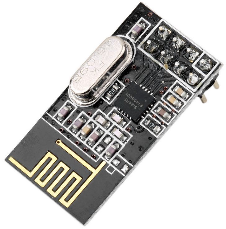
Hardware Overview
Radio Frequency
The nRF24L01+ module is designed to operate in the 2.4 GHz worldwide ISM frequency band and uses GFSK modulation for data transmission. The data transfer rate is configurable and can be set to 250kbps, 1Mbps, or 2Mbps.
Power
The module’s operating voltage ranges from 1.9 to 3.9V. Please keep in mind that powering the module with 5V will most likely damage your nRF24L01+ module.
Despite the fact that the module operates at 1.9V to 3.6V, the logic pins are 5-volt tolerant, so you do not need a logic level translator.
The output power of the module can be programmed to be 0 dBm, -6 dBm, -12 dBm, or -18 dBm. At 0 dBm, the module consumes only 12 mA during transmission, which is less than the consumption of a single LED.
And the best part is that it consumes only 26 µA in standby mode and 900 nA in power down mode. That’s why it’s the go-to wireless device for low-power applications.
SPI Interface
The nRF24L01+ communicates over a 4-pin SPI (Serial Peripheral Interface) with a maximum data rate of 10Mbps.
All parameters, including frequency channel (125 selectable channels), output power (0 dBm, -6 dBm, -12 dBm or -18 dBm), and data rate (250kbps, 1Mbps, or 2Mbps), can be configured through the SPI interface.
The SPI bus uses the concept of a master and a slave. In most of our projects, the Arduino serves as the master and the nRF24L01+ module serves as the slave.
Unlike the I2C bus, the SPI bus has a limited number of slaves. You can therefore use up to two SPI slaves (two nRF24L01+ modules) on a single Arduino.
Technical Specifications
Here are the specifications:
| Frequency Range | 2.4 GHz ISM Band |
| Maximum Air Data Rate | 2 Mb/s |
| Modulation Format | GFSK |
| Max. Output Power | 0 dBm |
| Operating Supply Voltage | 1.9 V to 3.6 V |
| Max. Operating Current | 13.5mA |
| Min. Current(Standby Mode) | 26µA |
| Logic Inputs | 5V Tolerant |
| Communication Range | 800+ m (line of sight) |
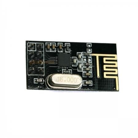
nRF24L01+ module -vs- nRF24L01+ PA/LNA module
The nRF24L01+ chip is used in a variety of modules, the two most common of which are listed below.
The first one uses an on-board antenna, which allows it to be more compact. A smaller antenna, however, means a shorter transmission range. You will be able to communicate over a distance of 100 meters using this module. Of course, that is outside in the open. Its range gets a little weaker inside the house, especially because of the walls.

The second one has an SMA connector and a duck antenna, but that’s not the only difference. It includes an RFX2401C range extender chip that combines PA, LNA, and transmit-receive switching circuitry. This enables the module to achieve a significantly greater transmission range of up to 1000 meters.

What exactly are PA and LNA?
PA stands for Power Amplifier. It merely amplifies the signal that is being transmitted by the nRF24L01+ chip. LNA stands for Low-Noise Amplifier, and its function is to amplify an extremely weak signal received from the antenna (usually below microvolts or -100 dBm) to a more useful level (usually around 0.5 to 1 V).

The receive path’s low-noise amplifier (LNA) and transmit path’s power amplifier (PA) connect to the antenna via a duplexer, which isolates the two signals and prevents the relatively powerful PA output from overloading the sensitive LNA input. Read this article on digikey.com for more information.
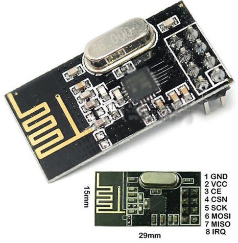
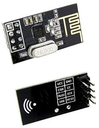
nRF24L01+ Module Pinout
Let’s take a look at the pinouts of both nRF24L01+ modules.

GND is the ground pin. It has a square marking to distinguish it from the other pins.
VCC supplies power to the module. It can range from 1.9 to 3.9 volts. You can connect it to your Arduino’s 3.3V output. Please keep in mind that connecting this to the 5V pin will most likely damage your nRF24L01+ module.
CE (Chip Enable) is an active-high pin. When enabled, the nRF24L01 will either transmit or receive, depending on the mode.
CSN (Chip Select Not) is an active-low pin that is typically held HIGH. When this pin goes low, the nRF24L01 begins listening for data on its SPI port and processes it accordingly.
SCK (Serial Clock) accepts clock pulses from the SPI bus master.
MOSI (Master Out Slave In) is the SPI input for the nRF24L01.
MISO (Master In Slave Out) is the SPI output of the nRF24L01.
IRQ is an interrupt pin that can notify the master when there is new data to process.
Wiring a nRF24L01+ module to an Arduino
Now that we know everything about how the nRF24L01+ module works, we can start hooking it up to our Arduino.
To begin, connect the module’s VCC pin to Arduino’s 3.3V and the GND pin to ground. CSN and CE pins can be connected to any digital pin on an Arduino; in our case, they are connected to digital pins #8 and #9.
Let’s wire up the SPI pins. Note that each Arduino board has a unique set of SPI pins that must be connected accordingly. For Arduino boards such as the UNO/Nano V3.0, these pins are digital 13 (SCK), 12 (MISO), 11 (MOSI) and 10 (SS).
If you’re using a different Arduino board, check the official documentation for SPI pin locations before proceeding.
The following table lists the pin connections:
| nRF24L01+ module | Arduino | |
| GND | GND | |
| VCC | 3.3V | |
| CE | 9 | |
| CSN | 8 | |
| SCK | 13 | |
| MOSI | 11 | |
| MISO | 12 |
The images below show how to connect the nRF24L01+ module to the Arduino.

Remember, you need to make two such circuits. One will act as a transmitter and the other as a receiver. Both have the same wiring.
Once you have connected everything, you are ready to go!
Library Installation
There are many libraries available for the nRF24L01+ module, but one of the most popular is RF24. This library has been around for a long time. It’s simple to use for beginners while still providing a lot for advanced users. We will use this library in our examples.
To install the library, navigate to Sketch > Include Library > Manage Libraries… Wait for the Library Manager to download the library index and update the list of installed libraries.

Filter your search by entering ‘rf24‘. Look for the library by TmRh20. Click on that entry and then choose Install.

Arduino Example Code – For Transmitter
//Include Libraries
#include <SPI.h>
#include <nRF24L01.h>
#include <RF24.h>

//create an RF24 object
RF24 radio(9, 8);  // CE, CSN

//address through which two modules communicate.
const byte address[6] = "00001";

void setup()
{
  radio.begin();

  //set the address
  radio.openWritingPipe(address);

  //Set module as transmitter
  radio.stopListening();
}
void loop()
{
  //Send message to receiver
  const char text[] = "Hello World";
  radio.write(&text, sizeof(text));

  delay(1000);
}
The examples below demonstrate how to set up a simple one-way link between a transmitter and a receiver. The transmitter simply sends a traditional ‘Hello World’ message to the receiver, which displays it in the Serial Monitor window.
This is the code we’ll use for our transmitter.
Arduino Example Code – For Receiver
This is the code we’ll use for our receiver.
//Include Libraries
#include <SPI.h>
#include <nRF24L01.h>
#include <RF24.h>

//create an RF24 object
RF24 radio(9, 8);  // CE, CSN

//address through which two modules communicate.
const byte address[6] = "00001";

void setup()
{
  while (!Serial);
    Serial.begin(9600);

  radio.begin();

  //set the address
  radio.openReadingPipe(0, address);

  //Set module as receiver
  radio.startListening();
}

void loop()
{
  //Read the data if available in buffer
  if (radio.available())
  {
    char text[32] = {0};
    radio.read(&text, sizeof(text));
    Serial.println(text);
  }
}