Description
This little module (HCMODU0083) is a breakout board for the IFR520 MOSFET transistor. The module is designed to switch heavy DC loads from a single digital pin of your microcontroller. Its main purpose is to provide a low cost way to drive a DC motor for robotics applications, but the module can be used to control most high current DC loads. Screw terminals are provided to interface to your load and external power source. An LED indicator provides a visual indication of when your load is being switched.
Specifications
- Size: 33*24mm
- Weight: 10g
- Voltage: 3.3V, 5V
- Ports: Digital Level
- Output load voltage :0-24V
- Output load current: <5A (1A above need to add heat sink)
- Platform: Arduino, MCU, ARM, raspberry pie
- Using original IRF520 Power MOS, you can adjust the output PWM
- Arduino drive up to 24V allows the load, such as LED lights, DC motors, miniature pumps, solenoid valves
- PWM dimming LED can be used to achieve stepless dimming, variable speed motor
Package Included:
- 1 x IRF520 MOS FET Driver Module
IRF520 MOSFET Driver Module Pinout
This sensor has 7 pins:
- VCC: Module power supply – 5V
- GND: Ground
- SIG: PWM input signal
- Vin: Input voltage 5-24 V
- OUT: Module output for connecting to motor
You can see the pinout of this module in the image below.

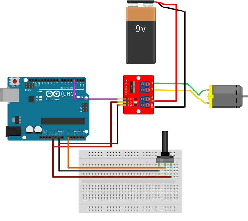
Required Materials
| Arduino UNO R3 | × | 1 |
| IRF520 MOSFET Driver Module | × | 1 |
| 6V DC Motor | × | 1 |
| 10K Potentiometer | × | 1 |
| 9V Battery | × | 1 |
| 9V Battery Clips with Bare Leads | × | 1 |
| Male-Female jumper wire | × | 1 |
| Male-Male jumper wire | × | 1 |
| 400 Tie point Breadboard | × | 1 |