


Description
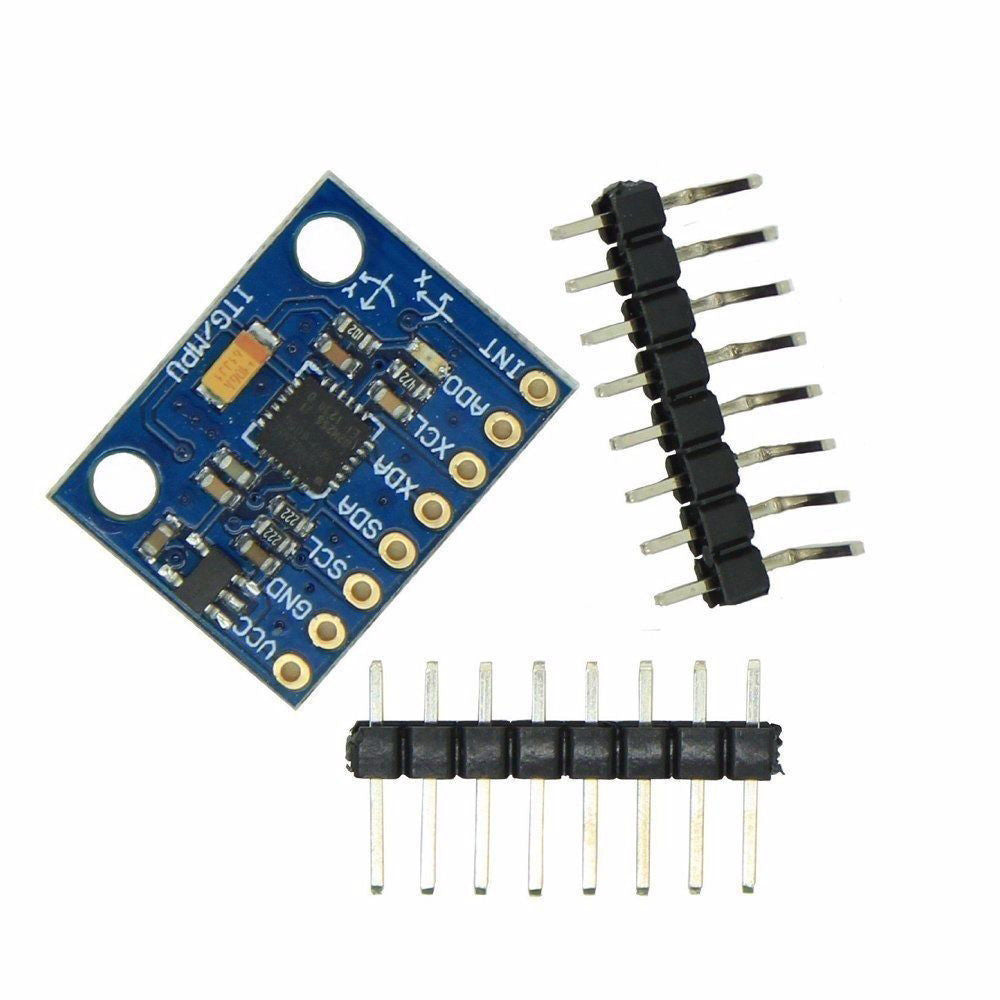
The GY-521 module is a breakout board for the MPU-6050 MEMS (Microelectromechanical systems) that features a 3-axis gyroscope, a 3-axis accelerometer, a digital motion processor (DMP), and a temperature sensor. The digital motion processor can be used to process complex algorithms directly on the board. Usually, the DMP processes algorithms that turn the raw values from the sensors into stable position data. This tutorial gives only a brief introduction to the GY-521/MPU-6050. In particular, it is shown how to retrieve the raw sensor values. The sensor values are retrieved by using the I2C serial data bus, which requires only two wires (SCL and SDA). If you plan to use the full range of features or require reliable and stable position data, then I recommend to have also a look at ready-to-use libraries. Please follow this link to find an excellent library with many examples: https://github.com/jrowberg/i2cdevlib/tree/master/Arduino/MPU6050.
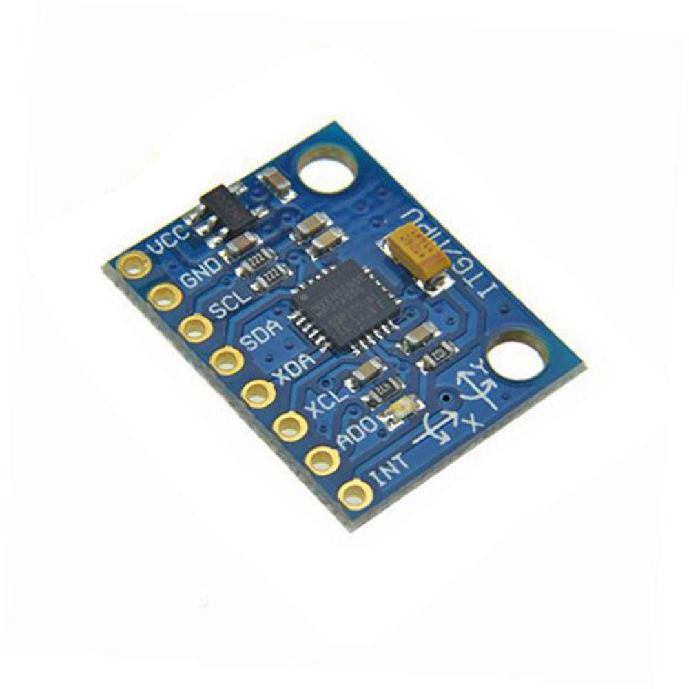
GY-521 Pin Layout
The GY-521 breakout has eight pins:
- VCC (The breakout board has a voltage regulator. Therefore, you can connect the board to 3.3V and 5V sources.)
- GND
- SCL (Serial Clock Line of the I2C protocol.)
- SDA (Serial Data Line of the I2C protocol.)
- XDA (Auxiliary data => I2C master serial data for connecting the module to external sensors.)
- XCL (Auxiliary clock => I2C master serial clock for connecting the module to external sensors.)
- AD0 (If this pin is LOW, the I2C address of the board will be 0x68. Otherwise, if the pin is HIGH, the address will be 0x69.)
- INT (Interrupt digital output)
Tutorial: How to use the GY-521 module (MPU-6050 breakout board) with the Arduino Uno