


Description:
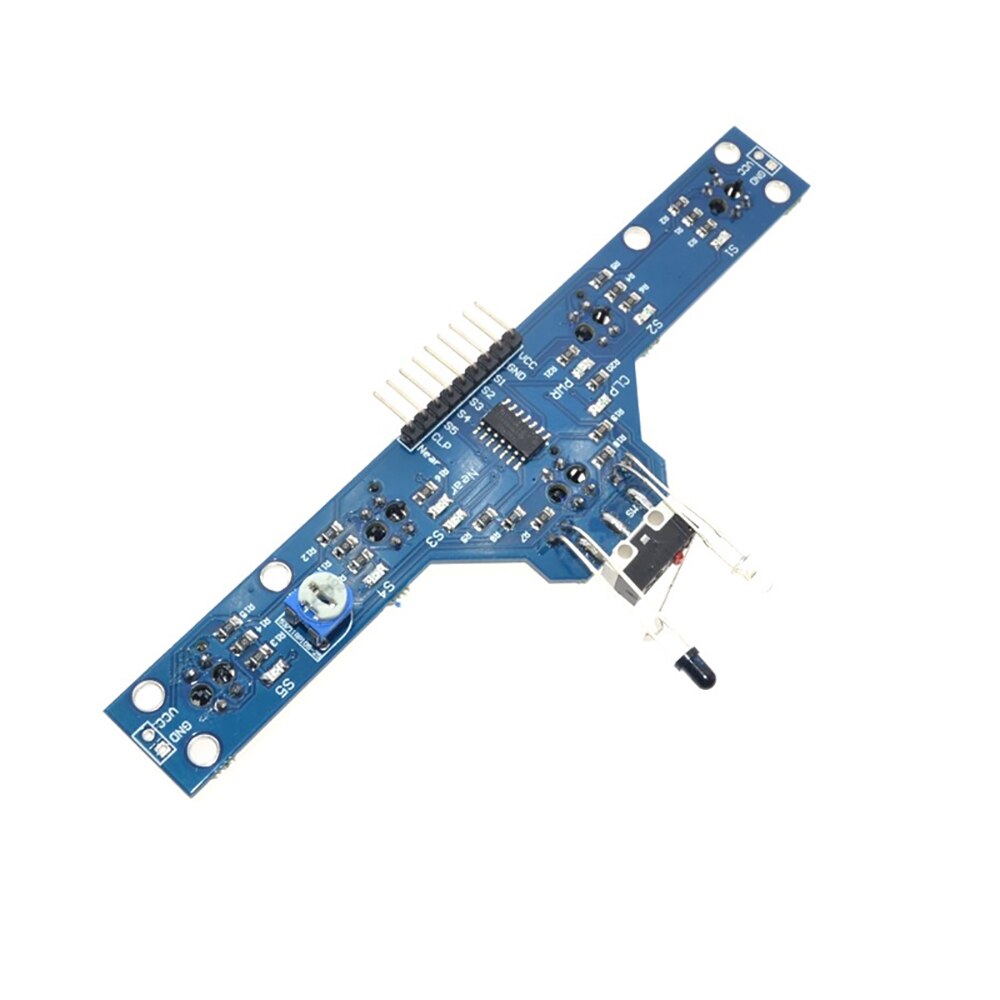
The BFD-1000 sensor module is a multi-sensor module that can be used to create a line follower robot that can accurately track a black or white line. The module is designed with 5 TCRT5000 sensors for line tracking and black road detection and an IR proximity sensor in the front. This combination of sensors makes it easy to create a robot that can accurately follow a line, even on complex tracks, The TCRT5000 sensors are designed to detect the contrast between a black line and a white background, which makes them ideal for line following. They have a detection range of 0-4cm, which means that they can detect the line even when it is very close to the ground. The sensors are also highly sensitive and can detect lines with a sensitivity range of 0.5mm-40mm without any adjustment. The front IR proximity sensor is designed to detect obstacles in front of the robot. It has an adjustable detection range of 0-5cm, which means that it can detect obstacles at varying distances. The sensor operates on an input voltage of 3.0V-5.5V and outputs digital signals (high and low level) that can be easily connected to a microcontroller. The module also has LED lights as indicators for easy debugging. The BFD-1000 sensor module is designed with a special touch sensor design, which simplifies the robot's design. The sensor outputs all digital signals, which makes it easy to connect to a microcontroller. The module also supports a voltage of 3.0-5.5V, which means that it can meet any system requirements.
Features:
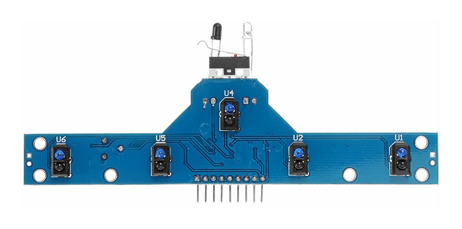
- 5 TCRT5000 sensors: The module has five TCRT5000 sensors that can be used to detect a black or white line. These sensors have a detection range of 0-4cm and are highly sensitive, making them ideal for line following.
- IR proximity sensor: The module also has an IR proximity sensor that can be used to detect obstacles in front of the robot. This sensor has an adjustable detection range of 0-5cm.
- Limit switch: The module has a limit switch that can be used to detect obstacles in front of the robot. This switch is designed to provide information to the robot in case the front sensor fails or there is an obstacle in front of it.
- Digital output: The module outputs digital signals (high and low level) that can be easily connected to a microcontroller.
- LED indicators: The module has LED lights that can be used as indicators for easy debugging.
- Wide voltage range: The module supports a voltage range of 3.0V-5.5V, which means that it can be used with a wide range of microcontrollers and other devices.
- Special touch sensor design: The module is designed with a special touch sensor design that makes it easy to use and connect to a microcontroller.
- High sensitivity: The module has a high sensitivity range of 0.5mm-40mm, which means that it can detect lines with high precision without requiring any adjustment.
Pinout of the Module:
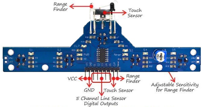
- VCC: This pin should be connected to a positive voltage supply between 3.0V and 5.5V.
- GND: This pin should be connected to the ground.
- S1: This pin is the output for the first TCRT5000 sensor.
- S2: This pin is the output for the second TCRT5000 sensor.
- S3: This pin is the output for the third TCRT5000 sensor.
- S4: This pin is the output for the fourth TCRT5000 sensor.
- S5: This pin is the output for the fifth TCRT5000 sensor.
- CLP: This pin is the output for the touch sensor.
- Range finder: This pin is the output for the front IR proximity sensor.
Circuit:
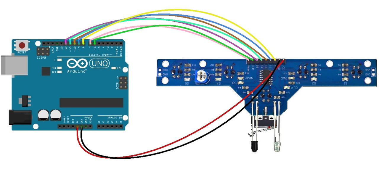
- VCC pin of the module to 5V pin of Arduino
- GND pin of the module to the GND pin of the Arduino
- S1 to digital pin 8 of Arduino
- S2 to digital pin 9 of Arduino
- S3 to digital pin 10 of Arduino
- S4 to digital pin 11 of Arduino
- S5 to digital pin 12 of Arduino
- CLP to digital pin 6 of Arduino
- Range finder sensor to digital pin 7
Code:
A basic code forreading the sensor values from the BFD-1000 module and displaying them over serial:
const int line_pin[5] = {8, 9, 10, 11, 12};
const int near_pin = 7;
const int clp_pin = 6;
int line_val[5] = {0};
int near_val = 0;
int clp_val = 0;

void setup() {
  Serial.begin(9600);
  for (int i = 0; i < 5; i++) {
    pinMode(line_pin[i], INPUT);
  }
  pinMode(near_pin, INPUT);
  pinMode(clp_pin, INPUT);
}

void loop() {
  read_sensor();
  display_serial();
}

void display_serial() {
  for (int i = 0; i < 5; i++) {
    Serial.print(line_val[i]);
    Serial.print(" ");
  }
  Serial.print(near_val);
  Serial.print(" ");
  Serial.println(clp_val);
  delay(1000);
}

void read_sensor() {
  for (int i = 0; i < 5; i++) {
    line_val[i] = digitalRead(line_pin[i]);
  }
  near_val = digitalRead(near_pin);
  clp_val = digitalRead(clp_pin);
}
- The first 6 lines of the code define the pins that the sensors are connected to. The 5-line sensors are connected to pins 8-12, the proximity sensor is connected to pin 7, and the touch sensor is connected to pin 6.
- In the setup function, the code initializes the serial communication with a baud rate of 9600 and sets the pin modes for the sensors as input.
- In the loop function, the code calls the read_sensor function and then the display_serial function.
- The read_sensor function uses a for loop to read the values of each of the 5 line sensors, the proximity sensor, and the touch sensor and stores these values in corresponding variables.
- The display_serial function then prints out the values of the sensors to the serial monitor. It does this by using another for loop to iterate through the line_val array and printing out each value, followed by printing the values of the proximity sensor and the touch sensor.
- The code then adds a delay of 1000ms (1 second) before starting over again.