Description
An ESP8266 Wi-Fi module is a SOC microchip mainly used for the development of end-point IoT (Internet of things) applications. It is referred to as a standalone wireless transceiver, available at a very low price. It is used to enable the internet connection to various applications of embedded systems.
Espressif systems designed the ESP8266 Wi-Fi module to support both the TCP/IP capability and the microcontroller access to any Wi-Fi network. It provides the solutions to meet the requirements of industries of IoT such as cost, power, performance, and design.
It can work as either a slave or a standalone application. If the ESP8266 Wi-Fi runs as a slave to a microcontroller host, then it can be used as a Wi-Fi adaptor to any type of microcontroller using UART or SPI. If the module is used as a standalone application, then it provides the functions of the microcontroller and Wi-Fi network.
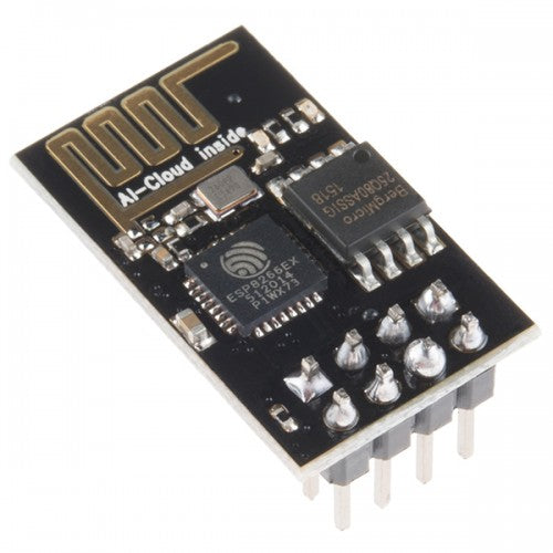
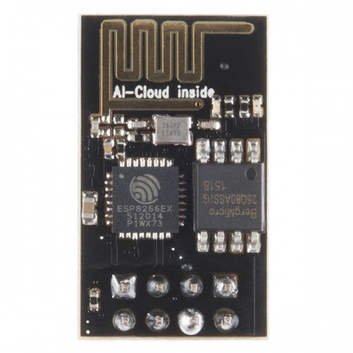
The ESP8266 Wi-Fi module is highly integrated with RF balun, power modules, RF transmitter and receiver, analog transmitter and receiver, amplifiers, filters, digital baseband, power modules, external circuitry, and other necessary components. The ESP8266 Wi-Fi module is a microchip shown in the figure below.
A set of AT commands are needed by the microcontroller to communicate with the ESP8266 Wi-Fi module. Hence it is developed with AT commands software to allow the Arduino Wi-Fi functionalities, and also allows loading various software to design the own application on the memory and processor of the module.
The processor of this module is based on the Tensilica Xtensa Diamond Standard 106 micro and operates easily at 80 MHz. There are different types of ESP modules designed by third-party manufacturers. They are,
- ESP8266-01 designed with 8 pins (GPIO pins -2)
- ESP8266-02 designed with 8 pins (GPIO pins -3)
- ESP8266-03 designed with 14 pins ( GPIO pins- 7)
- ESP8266-04 designed with 14 pins (GPIO pins- 7)
The ESP8266 Wi-Fi module comes with a boot ROM of 64 KB, user data RAM of 80 KB, and instruction RAM of 32 KB. It can support 802.11 b/g/n Wi-Fi network at 2.4 GHz along with the features of I2C, SPI, I2C interfacing with DMA, and 10-bit ADC. Interfacing this module with the microcontroller can be done easily through a serial port. An external voltage converter is required only if the operating voltage exceeds 3.6 Volts. It is most widely used in robotics and IoT applications due to its low cost and compact size.
ESP8266 Wi-Fi Module Specifications
The ESP8266 Wi-Fi module specifications or features are given below.
- It is a powerful Wi-Fi module available in a compact size at a very low price.
- It is based on the L106 RISC 32-bit microprocessor core and runs at 80 MHz
- It requires only 3.3 Volts power supply
- The current consumption is 100 m Amps
- The maximum Input/Output (I/O) voltage is 3.6 Volts.
- It consumes 100 mA current
- The maximum Input/Output source current is 12 mA
- The frequency of built-in low power 32-bit MCU is 80 MHz
- The size of flash memory is 513 kb
- It is used as either an access point or station or both
- It supports less than 10 microAmps deep sleep
- It supports serial communication to be compatible with several developmental platforms such as Arduino
- It is programmed using either AT commands, Arduino IDE, or Lua script
- It is a 2.4 GHz Wi-Fi module and supports WPA/WPA2, WEP authentication, and open networks.
- It uses two serial communication protocols like I2C (Inter-Integrated Circuit) and SPI ( Serial Peripheral Interface).
- It provides 10- bit analog to digital conversion
- The type of modulation is PWM (Pulse Width Modulation)
- UART is enabled on dedicated pins and for only transmission, it can be enabled on GPIO2.
- It is an IEEE 802.11 b/g/n Wi-Fi module with LNA, power amplifier, balun, integrated TR switch, and matching networks.
- GPIO pins – 17
- Memory Size of instruction RAM – 32 KB
- The memory size of instruction cache RAM – 32 KB
- Size of User-data RAM- 80 KB
- Size of ETS systems-data RAM – 16 KB
ESP8266 Pinout
Here’s the ESP-01 pinout.

ESP8266 Wi-Fi example using the Arduino IDE
In the following examples, I will be using the NodeMCU development board and will program it with the Arduino software. Hopefully you have already set-up your ESP8266 development environment and were able to load the blink sketch. If not please follow this tutorial first.
ESP8266 WiFi station mode example
The ESP8266 can communicate over WiFi in two different modes. It can connect to an existing wireless hot spot, or access point, similar to the way you connect your phone or computer to the Internet. This is called “station” mode. In station mode the ESP8266 board can reach out to the internet and may also communicate with other devices connected to the same network, including other ESP8266 modules. Here is a simple example. Remember to replace the values for the ssid and password variables with the name and password for your wireless network!
/*
**  Connect the ESP8266 unit to an existing WiFi access point
**  For more information see http://42bots.com
*/

#include

// Replace these with your WiFi network settings
const char* ssid = "ESP8266"; //replace this with your WiFi network name
const char* password = "ESP8266Test"; //replace this with your WiFi network password

void setup()
{
  delay(1000);
  Serial.begin(115200);

  WiFi.begin(ssid, password);

  Serial.println();
  Serial.print("Connecting");
  while (WiFi.status() != WL_CONNECTED)
  {
    delay(500);
    Serial.print(".");
  }

  Serial.println("success!");
  Serial.print("IP Address is: ");
  Serial.println(WiFi.localIP());
}

void loop() {
}

Once you load the code on your ESP8266 module, open the serial monitor and restart the module (pressing the reset button on the NodeMCU board will do the trick). All of the code executes in the set-up function, so it will only run once. You should see something like this, if all is well:
If you have access to your router admin screen, you should see the ESP8266 module in the list of connected devices.

