Description
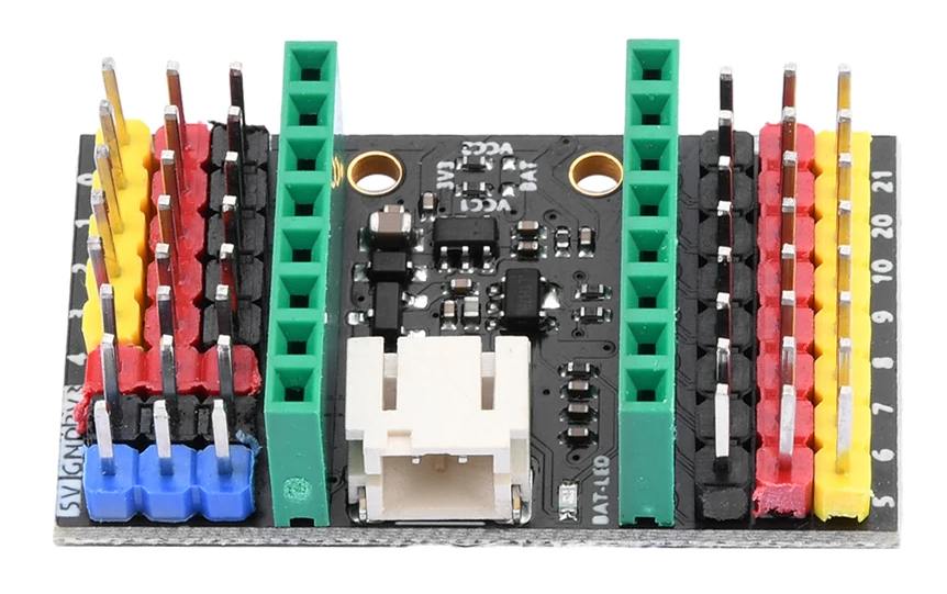
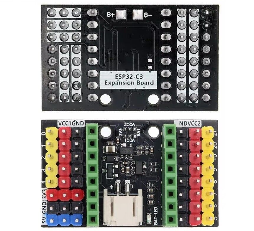
The ESP32-C3-SuperMini expansion board is specially designed for the ESP32-C3-SuperMini development board. It makes up for many shortcomings of the ESP32-C3-SuperMini development board. Using the expansion board, you can connect an external 3.7V lithium battery and support charging the lithium battery through USB. There is a green indicator while charging. When the green indicator light goes out, the lithium battery is fully charged.
This extension board makes all 10 ports accessible, which makes it convenient for users to install various sensors.
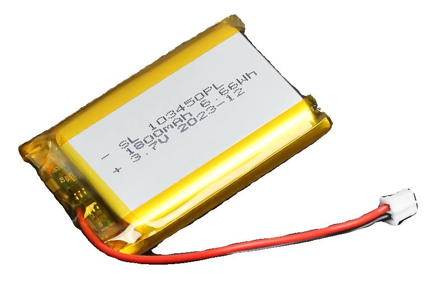
The ESP32C3supermini expansion board can be connected to a 3.7V lithium battery (PH2.0 interface lithium battery) as in following picture.
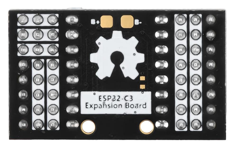
The ESP32C3supermini expansion board provides users with a better power supply solution. The expansion board has two power supplies, VCC1 and VCC2. The default voltage output by VCC1 and VCC2 is 3.3V. When you need to output a higher voltage, you can short-circuit the PCB (as shown below). At this time, the voltage output by VCC1 and VCC2 is the power supply voltage 3.7V. The default 0R resistor used at the factory is connected to 3.3V. If you need to output 3.7V, directly remove the 0R resistor and short-circuit the three pads with tin. VCC1 and VCC2 control the voltage output respectively. If you need to use one, just deal with it. Whichever one will do.
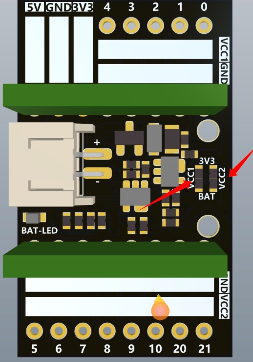
Chips on this board
To interprete the markings on SMD components, the following website is helpful: https://www.s-manuals.com/smd
I see the following markings on the chips on the expansion board:
S201
- Marking (SMDcode):
- (logo) S201
- Package:
- SOT23-5
Probably not a R5220K201A, which is a "PWM Step-down DC/DC Converter with switch function" and is marked S201, but has 6 pins, and not available in SOT23 package.
Maybe this is a LA9010 from INNO-Tech, a charger circuit for a 4.2V battery. Is this correct?
