

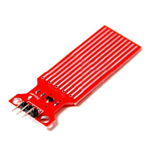
Pinout

Water Liquid Level Sensor Pin Connections with microcontrollers
- VCC ↔ 3.0V ~ 5.0V
- GND ↔ power supply ground
- AOUT ↔ MCU’s I/O (analog output)
How Does a Water Level Sensor Work?
The operation of the water level sensor is fairly simple.
The power and sense traces form a variable resistor (much like a potentiometer) whose resistance varies based on how much they are exposed to water.

This resistance varies inversely with the depth of immersion of the sensor in water:
- The more water the sensor is immersed in, the better the conductivity and the lower the resistance.
- The less water the sensor is immersed in, the poorer the conductivity and the higher the resistance.
The sensor generates an output voltage proportional to the resistance; by measuring this voltage, the water level can be determined.
Wiring a Water Level Sensor to an Arduino
Let’s hook up the water level sensor to the Arduino.
To begin, connect the + (VCC) pin on the module to 5V on the Arduino and the – (GND) pin to ground.
One well-known issue with these sensors is that they have a shorter lifespan because they are constantly exposed to moisture. Moreover, constantly applying power to the sensor while immersed in water significantly accelerates the rate of corrosion.
To avoid this, it is recommended that the sensor be turned on only when taking readings.
One easy way to do this is to connect the sensor’s power pin to a digital pin on an Arduino and set it to HIGH or LOW as needed. So, we’ll connect the + (VCC) pin to the Arduino’s digital pin #7.
Finally, connect the S (Signal) pin to the Arduino’s A0 ADC pin.
The wiring is shown in the image below.

Basic Arduino Example
After constructing the circuit, upload the following sketch to your Arduino.
// Sensor pins
#define sensorPower 7
#define sensorPin A0

// Value for storing water level
int val = 0;

void setup() {
	// Set D7 as an OUTPUT
	pinMode(sensorPower, OUTPUT);

	// Set to LOW so no power flows through the sensor
	digitalWrite(sensorPower, LOW);

	Serial.begin(9600);
}

void loop() {
	//get the reading from the function below and print it
	int level = readSensor();

	Serial.print("Water level: ");
	Serial.println(level);

	delay(1000);
}

//This is a function used to get the reading
int readSensor() {
	digitalWrite(sensorPower, HIGH);	// Turn the sensor ON
	delay(10);							// wait 10 milliseconds
	val = analogRead(sensorPin);		// Read the analog value form sensor
	digitalWrite(sensorPower, LOW);		// Turn the sensor OFF
	return val;							// send current reading
}
After uploading the sketch, open the Serial Monitor window to view the output. When the sensor is dry, it will output a value of 0; however, as the sensor is immersed in water, the output will gradually increase.

Code Explanation:
The sketch begins with the declaration of the Arduino pins to which the sensor’s + (VCC) and S (signal) pins are connected.
#define sensorPower 7
#define sensorPin A0
Following that, we define a variable val to store the current water level.
int val = 0;In the Setup section, we first configure the sensor’s power connection to behave as an output, then we set it low to keep the sensor off initially. We establish serial communication as well.
pinMode(sensorPower, OUTPUT);
digitalWrite(sensorPower, LOW);
Serial.begin(9600);
In the loop section, we call the readSensor() custom function once every one second and print the result.
Serial.print("Water level: ");
Serial.println(readSensor());
delay(1000);
The readSensor() custom function simply turns on the sensor, waits 10 milliseconds, reads the analog value from the sensor, turns it off, and returns the analog value.
int readSensor() {
	digitalWrite(sensorPower, HIGH);
	delay(10);
	val = analogRead(sensorPin);
	digitalWrite(sensorPower, LOW);
	return val;
}
Finding the threshold values
To estimate the water level, record the values of your sensor output when the sensor is completely dry, partially immersed, and fully immersed in water.
Simply run the above sketch and take your readings.
Keep in mind that your sensor may be more or less sensitive depending on the type of water you use. As you may know, pure water is not conductive; it is the minerals and impurities in water that make it conductive.
When you run the sketch, you should see readings similar to the ones below:
- when the sensor is dry (0)
- when the sensor is partially immersed in water (~420)
- when the sensor is fully immersed in water (~520)

This test may require some trial and error. Once you have the readings, you can use them as a threshold to trigger an action.