Description
The Heart Rate Monitor Kit with AD8232 ECG sensor module Kit For Arduino is a cost-effective board use to measure the electrical activity of the heart. This electrical activity can be chart as an ECG or Electrocardiogram and output as an analog reading.
ECGs can be extremely noisy, the AD8232 Single Lead Heart Rate Monitor acts as an op-amp to help obtain a clear signal from the PR and QT Intervals easily. The ECG module AD8232 heart ECG monitoring sensor module is an integrated signal conditioning block for ECG and other bio-potential measurement applications.
The ECG Module AD8232 Heart ECG Monitoring Sensor Module Kit for Arduino is designed to extract, amplify, and filter small bio-potential signals in the presence of noisy conditions; such as those created by motion or remote electrode placement.
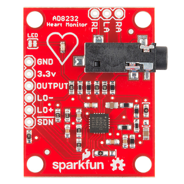
The AD8232 Heart Rate Monitor breaks out nine connections from the IC that you can solder pins, wires, or other connectors too. SDN, LO+, LO-, OUTPUT, 3.3V, GND provide essential pins for operating this monitor with an Arduino or other development board.
Also provided on this board are RA (Right Arm), LA (Left Arm), and RL (Right Leg) pins to attach and use your own custom sensors. Additionally, there is an LED indicator light that will pulsate to the rhythm of a heartbeat. Biomedical Sensor Pads and Sensor Cable are required to use the heart monitor and can be found in the Recommended Products section.
Pin Connections
The AD8232 Heart Rate Monitor breaks out nine connections from the IC. We traditionally call these connections "pins" because they come from the pins on the IC, but they are actually holes that you can solder wires or header pins to.
We'll connect five of the nine pins on the board to your Arduino. The five pins you need are labeled GND, 3.3v, OUTPUT, LO-, and LO+.
| Board Label | Pin Function | Arduino Connection |
| GND | Ground | GND |
| 3.3v | 3.3v Power Supply | 3.3v |
| OUTPUT | Output Signal | A0 |
| LO- | Leads-off Detect - | 11 |
| LO+ | Leads-off Detect + | 10 |
| SDN | Shutdown | Not used |
Application
- Fitness and exercise heart rate monitoring
- Portable ECG
- Remote health care
- Gaming peripherals
- Biological signal acquisition
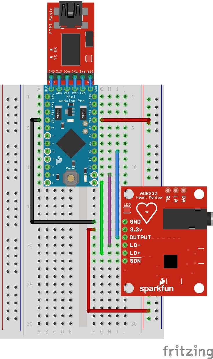
Circuit Diagram
Follow the diagram below, to make necessary connections. The SDN pin is not used in this demo. Connecting this pin to ground or "LOW" on a digital pin will power down the chip. This is useful for low power applications.
Sensor Pad Placement
Now that the electronics are complete, let's look at sensor pad placement. It is recommended to snap the sensor pads on the leads before application to the body.
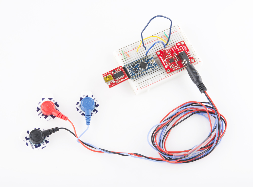
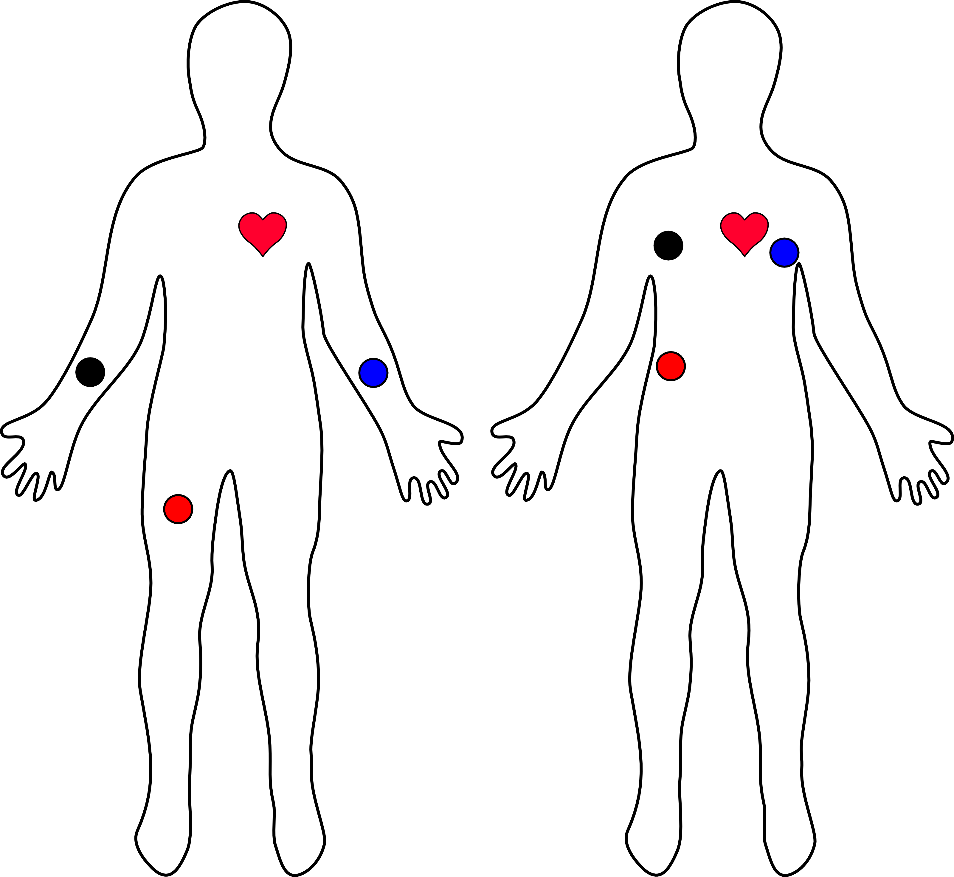
The closer to the heart the pads are, the better the measurement. The cables are color coded to help identify proper placement as shown in the table based on Einthoven's triangle. The sensors can be placed on the forearms and leg as shown on the diagram on the left. Or they can be placed on the chest near the arms and above the right, lower abdomen (i.e. just above the right hip) as shown on the diagram on the right.
| Cable Color | Signal |
| Black | RA (Right Arm) |
| Blue | LA (Left Arm) |
| Red | RL (Right Leg) |
Code
void setup() {
  // initialize the serial communication:
  Serial.begin(9600);
  pinMode(10, INPUT); // Setup for leads off detection LO +
  pinMode(11, INPUT); // Setup for leads off detection LO -

}

void loop() {

  if((digitalRead(10) == 1)||(digitalRead(11) == 1)){
    Serial.println('!');
  }
  else{
    // send the value of analog input 0:
      Serial.println(analogRead(A0));
  }
  //Wait for a bit to keep serial data from saturating
  delay(1);
}
Output
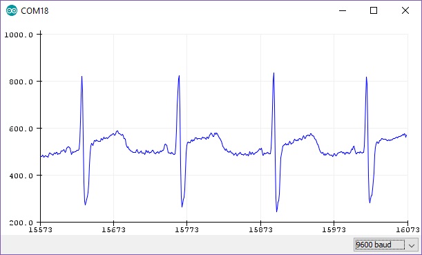
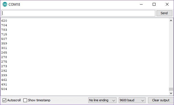
To verify that the heart rate monitor is working as expected, open the serial monitor at 9600 baud. You should see values printed on the screen. Below is an example output with the sensors connected on the forearms and right leg. Your serial output should spike between +300/-200 around the center value of about ~500.
The serial data is hard to visualize if you are just viewing the values. If you are using Arduino IDE v1.6.6+, there is an option to view the data on a graph using the Arduino Serial Plotter as one option. In the Arduino IDE, select Tools > Serial Plotter. You should see a waveform similar to the image below when the sensors are placed correctly and not moving.