


Description
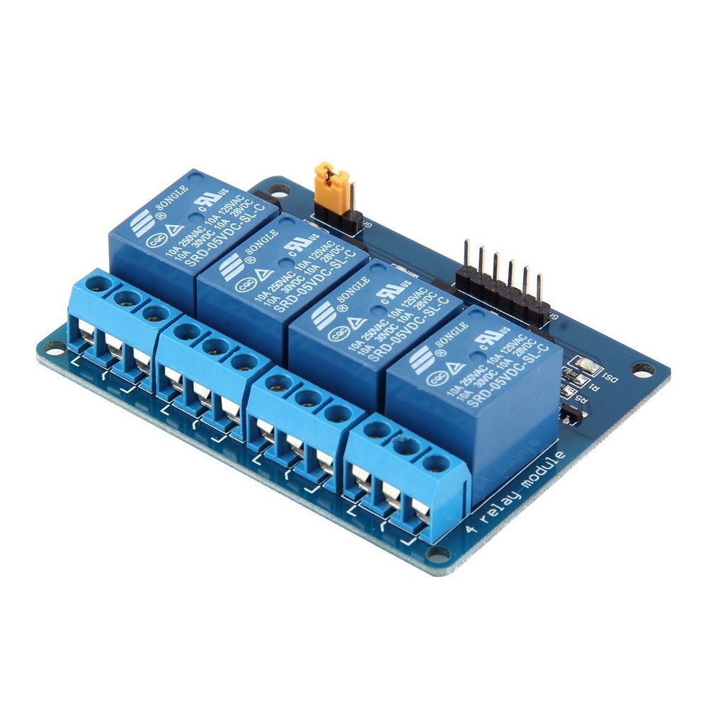
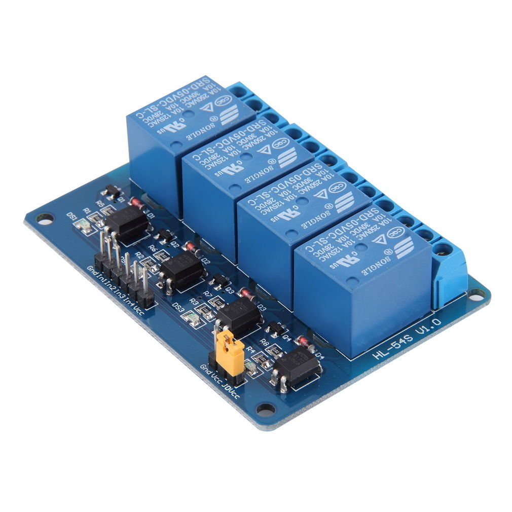
The four-channel relay module contains four 5V relays and the associated switching and isolating components, which makes interfacing with a microcontroller or sensor easy with minimum components and connections. The contacts on each relay are specified for 250VAC and 30VDC and 10A in each case, as marked on the body of the relays.
Features:
- This relay module is 5V active low.
- It is an 4-channel relay interface board, which can be controlled directly by a wide range of microcontrollers such as Arduino, AVR, raspberry pi, PIC, ARM, PLC, etc.
- It is also able to control various appliances and other equipments with large current.
- Relay output maximum contact is AC250V 10A and DC30V 10A.
- Standard interface can be directly connected with microcontrollers.
- Red working status indicator lights are conducive to the safe use.
- Widely used for all MCU control, industrial sector, PLC control, smart home control.
Specifications:
- Working voltage: 5V
- Channel: 4 channel
- Color: Blue
- size: approx. 7.1 x 5.3 x 1.8cm
- Net weight: 56.1g
Package includes:
- 1 x 4 Channel Relay Module
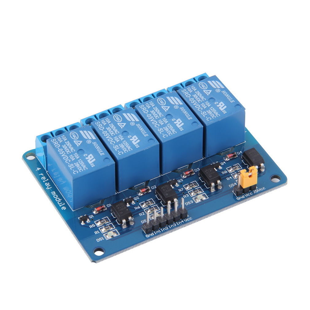
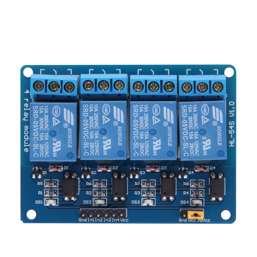
Pinout

|
Pin Number |
Pin Name |
Description |
|
1 |
GND |
Ground reference for the module |
|
2 |
IN1 |
Input to activate relay 1 |
|
3 |
IN2 |
Input to activate relay 2 |
|
4 |
IN3 |
Input to activate relay 3 |
|
5 |
IN4 |
Input to activate relay 4 |
|
6 |
VCC |
Power supply for the relay module |
|
7 |
VCC |
Power supply selection jumper |
|
8 |
JD-VCC |
Alternate power pin for the relay module |
Wiring
Make connections according to the circuit diagram given below.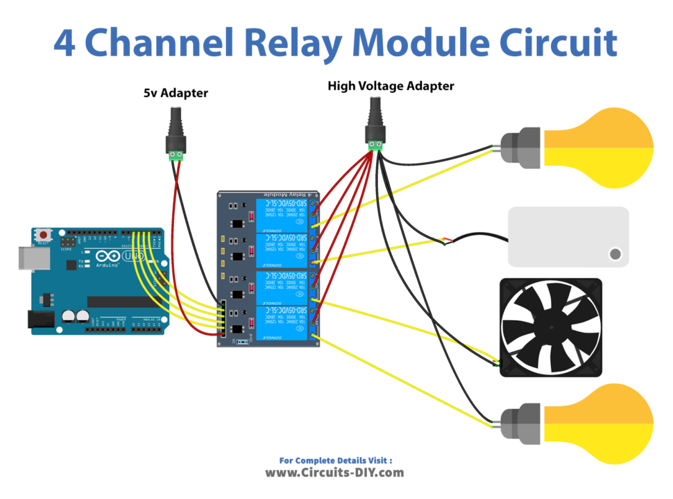
Wiring / Connection
| Arduino | Relay Module |
|---|---|
| GND | DC- |
| 5V | DC+ |
| D2 | IN1 |
| D3 | IN2 |
| D4 | IN3 |
| D5 | IN4 |
Code
Now copy the following code and upload it to Arduino IDE Software.
#define PIN_RELAY_1  2 // the Arduino pin, which connects to the IN1 pin of relay module
#define PIN_RELAY_2  3 // the Arduino pin, which connects to the IN2 pin of relay module
#define PIN_RELAY_3  4 // the Arduino pin, which connects to the IN3 pin of relay module
#define PIN_RELAY_4  5 // the Arduino pin, which connects to the IN4 pin of relay module

// the setup function runs once when you press reset or power the board
void setup() {
  Serial.begin(9600);

  // initialize digital pin as an output.
  pinMode(PIN_RELAY_1, OUTPUT);
  pinMode(PIN_RELAY_2, OUTPUT);
  pinMode(PIN_RELAY_3, OUTPUT);
  pinMode(PIN_RELAY_4, OUTPUT);
}

// the loop function runs over and over again forever
void loop() {
  Serial.println("Turn on all");
  digitalWrite(PIN_RELAY_1, HIGH);
  digitalWrite(PIN_RELAY_2, HIGH);
  digitalWrite(PIN_RELAY_3, HIGH);
  digitalWrite(PIN_RELAY_4, HIGH);
  delay(1000);

  Serial.println("Turn off all");
  digitalWrite(PIN_RELAY_1, LOW);
  digitalWrite(PIN_RELAY_2, LOW);
  digitalWrite(PIN_RELAY_3, LOW);
  digitalWrite(PIN_RELAY_4, LOW);
  delay(1000);
}
Working Explanation
The first step is to connect the SSR module to the Arduino according to the pinout diagram provided by the manufacturer. The control pins of the SSR module (IN1, IN2, IN3, IN4) are connected to digital pins on the Arduino and the module’s power and ground pins are connected to the appropriate power and ground pins on the Arduino.
In the code, the pin numbers for the control pins of the SSR module and the appliances are defined and the pin modes are set in the setup function. In the loop function, the code uses the digital write function to control the appliances using the control pins of the SSR module. For example, to turn on the AC bulb, the code would write a high signal to the IN1 pin of the SSR module. To turn off the AC bulb, the code would write a low signal to the IN1 pin of the SSR module.