
Description
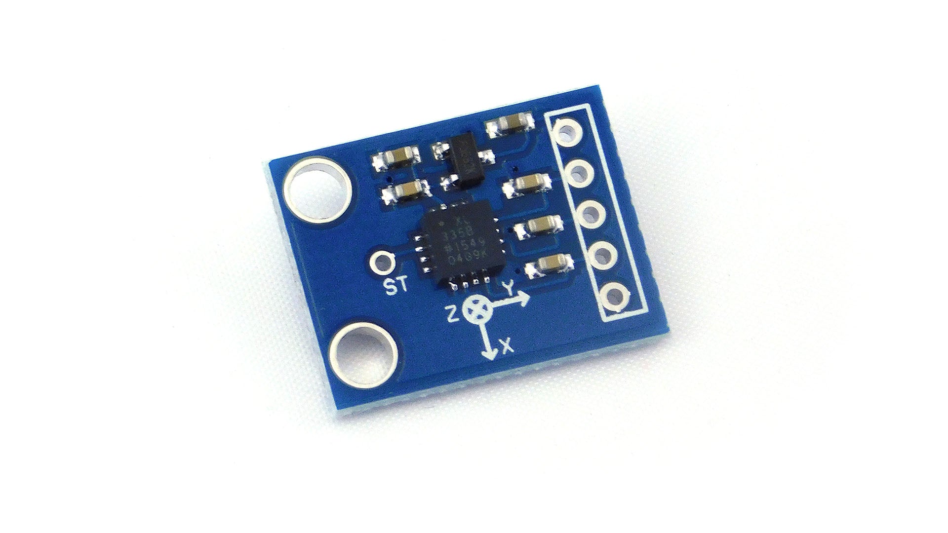
GY-61 DXL335 3-Axis Accelerometer Module Is AThe ADXL335 Is A Low-Power, 3-Axis Accelerometer With Signal Conditioned Voltage Outputs. It Can Measure The Static Acceleration Of Gravity In Tilt Sensing Applications, As Well As Dynamic Acceleration Resulting From Motion, Shock, Or Vibration. The User Selects The Bandwidth Of The Accelerometer Using The CX, CY, And CZ Capacitors At The XOUT, YOUT, And ZOUT Pins. Bandwidths Can Be Selected To Suit The Application, With A Range Of 0.5 Hz To 1600 Hz For X And Y Axes, And A Range Of 0.5 Hz To 550 Hz For The Z-Axis. The Sensor Has A Full Sensing Range Of +/-3g.
There is an on-board 3.3V voltage regulator to power the ADXL335 so the power provided should be between 3.3V and 6V DC.
Wiring the GY-61 ADXL335 Module to the Arduino:
The analog accelerometer outputs are connected to the Arduino analog inputs, X to A0, Y to A3, and Z to A4. The Arduino 3.3V output is used to provide power to Vcc and the GND is connected to the ground.
For the analog inputs, the Arduino uses a reference voltage to convert the input voltage to a value. Normally this is the internal 5V supply. Because we are powering the sensor from the 3.3V we need to provide a reference voltage by feeding the 3.3V into the Arduino AREF input.
The GY-61 ADXL335 Calibration:
Calibration is based around the assumption that the sensor response is linearly proportional to the acceleration, and that we know three values of acceleration for which we can measure the sensor response on each of the axes.
When the sensor is at rest, positioned flat on a horizontal surface then the Z-axis will be measuring the force of gravity - 1g - and the X and Y sensors will each be measuring zero. If we then flip the sensor upside-down we can measure negative 1g on the Z-axis. The sensor can be rotated so that each of the axes is, in turn, parallel to the force of gravity and reading for zero acceleration, 1g and -1g obtained for each axis.
Code:
const int xpin = A0; // x-axis of the accelerometer
const int ypin = A3; // y-axis
const int zpin = A4; // z-axis
void setup()
{
Serial.begin(9600);
}
void loop()
{
int x = analogRead(xpin); //read from xpin
delay(1); //
int y = analogRead(ypin); //read from ypin
delay(1);
int z = analogRead(zpin); //read from zpin
float zero_G = 512.0; //ADC is 0~1023 the zero g output equal to Vs/2
float scale = 102.3; //ADXL335330 Sensitivity is 330mv/g
//330 * 1024/3.3/1000
Serial.print(((float)x - 331.5)/65*9.8); //print x value on serial monitor
Serial.print("\t");
Serial.print(((float)y - 329.5)/68.5*9.8); //print y value on serial monitor
Serial.print("\t");
Serial.print(((float)z - 340)/68*9.8); //print z value on serial monitor
Serial.print("\n");
delay(1000); //wait for 1 second
}