


Description
SIM900 GSM/GPRS shield serves as a solid launching point for you to get started with IoT. SIM900 GSM/GPRS Shield is a GSM modem that can be integrated into a great number of IoT projects. You can use this shield to accomplish almost anything a normal cell phone can: SMS text messages, making or receiving phone calls, connecting to the internet through GPRS, TCP/IP, and more.
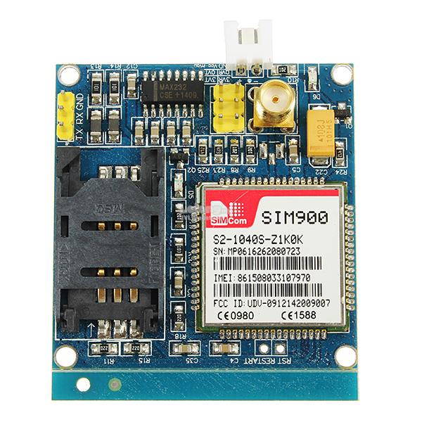
The GPRS Shield is based on the SIM900 module from SIMCOM and compatible with Arduino and its clones.
The shield allows you to achieve SMS, MMS, GPRS, and audio via UART by sending AT commands (GSM 07.07, 07.05, and SIMCOM enhanced AT Commands).
The shield also has the 12 GPIOs, 2 PWMs, and an ADC of the SIM900 module (they are all 2V8 logic) present onboard.
Features
- Quad-Band 850, 900, 1800, and 1900 MHz would work on GSM networks in all countries across the world.
- GPRS multi-slot class 10/8
- GPRS mobile station class B
- Compliant to GSM phase 2/2+
- Class 4 (2 W @ 850 / 900 MHz)
- Class 1 (1 W @ 1800 / 1900MHz)
- Control via AT commands: Standard Commands: GSM 07.07 & 07.05; Enhanced Commands: SIMCOM AT Commands.
- Short Message Service: so that you can send small amounts of data over the network (ASCII or raw hexadecimal).
- The embedded TCP/UDP stack allows you to upload data to a web server.
- RTC supported.
- Selectable serial port.
- Speaker and headphone jacks.
- Low power consumption: 1.5 mA (sleep mode)
- Industrial Temperature Range: -40°C ~ +85 °C
Applications
- M2M (machine-to-machine) applications
- Remote control of appliances
- A remote weather station or a wireless sensor network
- Vehicle tracking system with a GPS module
Package Includes
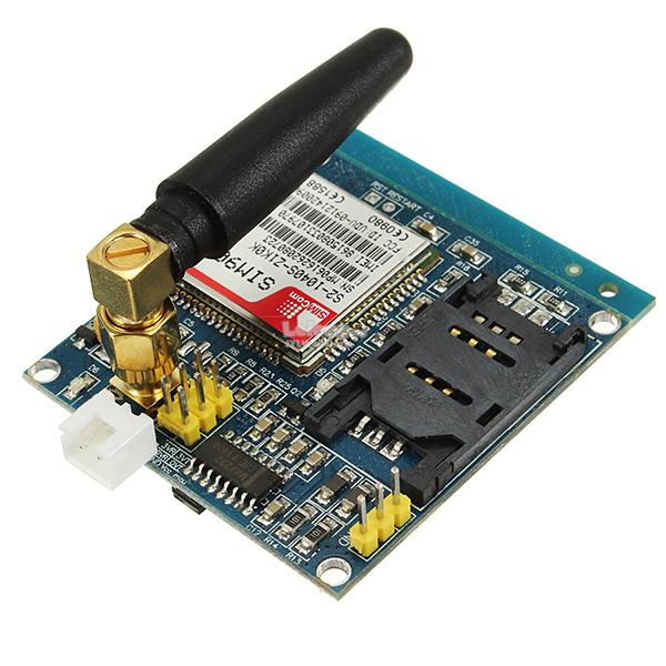
- 1 x SIM900 Board
- 1 x Antenna
Required Materials
| Arduino UNO R3 |
| SIM900 GSM GPRS Quad-Band Development Module |
First, you must add the library. Download the Zip file, and add the file to Arduino IDE. Go to Sketch tab, Include library and Add ZIP Library. If it is the first time you are using an Arduino board, just follow these steps:
- Go to www.arduino.cc/en/Main/Software and download the Arduino software compatible to your OS. Install the IDE software as instructed.
- Run the Arduino IDE and clear the text editor and copy the following code in the text editor.
- Choose the board in tools and boards, select your Arduino Board.
- Connect the Arduino to your PC and set the COM port in tools and port.
- Press the Upload (Arrow sign) button.
- You are all set!
- Necessary Files and Downloads: SIM900 Arduino Shield
#include "SIM900.h"
#include "SoftwareSerial.h"
//#include "inetGSM.h"
//#include "sms.h"
//#include "call.h"

//To change pins for Software Serial, use the two lines in GSM.cpp.

//GSM Shield for Arduino
//this code is based on the example of Arduino Labs.

//Simple sketch to communicate with SIM900 through AT commands.

//InetGSM inet;
//CallGSM call;
//SMSGSM sms;

int numdata;
char inSerial[40];
int i=0;


void setup()
{
     //Serial connection.
     Serial.begin(9600);
     Serial.println("GSM Shield testing.");
     //Start configuration of shield with baudrate.
     //For http uses is raccomanded to use 4800 or slower.
     if (gsm.begin(9600))
          Serial.println("\nstatus=READY");
     else Serial.println("\nstatus=IDLE");
};

void loop()
{
     //Read for new byte on serial hardware,
     //and write them on NewSoftSerial.
     serialhwread();
     //Read for new byte on NewSoftSerial.
     serialswread();
};

void serialhwread()
{
     i=0;
     if (Serial.available() > 0) {
          while (Serial.available() > 0) {
               inSerial[i]=(Serial.read());
               delay(10);
               i++;
          }

          inSerial[i]='\0';
          if(!strcmp(inSerial,"/END")) {
               Serial.println("_");
               inSerial[0]=0x1a;
               inSerial[1]='\0';
               gsm.SimpleWriteln(inSerial);
          }
          //Send a saved AT command using serial port.
          if(!strcmp(inSerial,"TEST")) {
               Serial.println("SIGNAL QUALITY");
               gsm.SimpleWriteln("AT+CSQ");
          } else {
               Serial.println(inSerial);
               gsm.SimpleWriteln(inSerial);
          }
          inSerial[0]='\0';
     }
}

void serialswread()
{
     gsm.SimpleRead();
}
It’s simple to communicate with SIM900 through AT commands.
AT commands are commands for controlling modems. AT commands are actually derived from Hayes Command. All commands AT commands start with AT.
Be careful that AT is a prefix that receives a syntax and is not a command name. For example, one of the CMC + CMCAM commands is called AT + CMGS. There is another command called D that is sent to the modem as ATD.
Many GSM, GPRS, Bluetooth, and some other modules use AT commands for communication with computers and microcontrollers.
You can download all AT commands from Here.
Necessary Files and Downloads: SIM900 AT Commands
Finally, this command gets location, time and date. Note that for searching the location in google map, you must change (x,y) coordinates order to (y,x).
Look at the GIF for more details.
