

Description
The MAX485 TTL to RS-485 Interface Module allows MCUs to use the RS-485 differential signaling for robust long distance serial communications.
RS-485 provides for robust serial communications over long distances of up to 1200 meters (4000′) or in electrically noisy environments and is commonly used in industrial environments. It supports up to 2.5MBit/Sec data rates, but as distance goes up, the maximum data rate that can be supported comes down.
You can think of RS-485 as RS232 on steroids. The data starts out as typical TTL level serial as far as the microcontroller is concerned while the RS-485 module takes care of converting the electrical signals between TTL and the differential signaling used by RS-485.
Features of MAX485 TTL To RS-485 Interface Module
- Use MAX485 Interface chip
- Uses differential signaling for noise immunity
- Distances up to 1200 meters
- Speeds up to 2.5Mbit/Sec
- Multi-drop supports up to 32 devices on same bus
- Red power LED
- 5V operation
Package Included:
- 1 x MAX485 RS-485 TTL to RS485 MAX485CSA Converter Module For Arduino
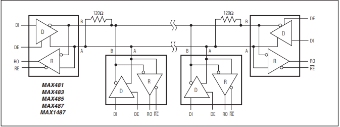
Multi-Drop Support for Multiple Devices
A significant benefit of RS-485 is that it supports multiple devices (up to 32) on the same cable, commonly referred to as ‘multi-drop’.
This works by passing the bus through each device where it picks off the signal as it passes through as shown below.
These devices are typically setup in a Master / Slave configuration with one Master and one or more Slave devices. Since they all share the same bus, to avoid conflict the Slave devices only talk when they are asked for something by the Master such as requesting a temperature reading.
Differential Signaling
The RS-485 uses differential signaling and requires only 2 wires and a common ground.
Differential signals operate by putting the signal on 1 wire and the inverse of the signal on the other wire. This improves the signals noise immunity and the ability to recover the signal at the far end of the cable as noise tends to couple into both lines equally and therefore cancels out at the receiving end.
Wiring RS-485
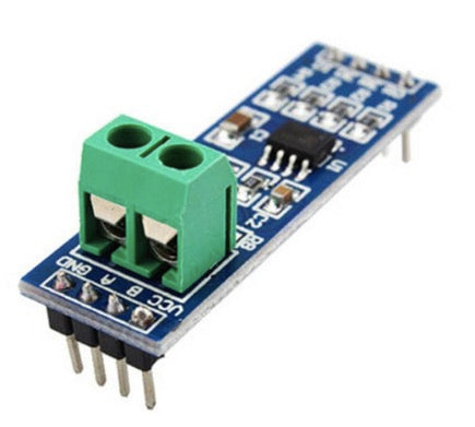
These two differential data lines are labeled as A & B. On the module, these are available on the screw terminal block as well as the two center pins on that end of the module.
When connecting the modules together, the wiring is straight through, so A on one end should be connected to A on the other end and B connects to B.
The wires should ideally be twisted pair. Using twisted pair becomes more important for longer runs or where there is a lot of electrical noise. For simple breadboard testing or other short runs, it is not necessary. A common ground is needed, but this can often be provided by the earth ground at each end for shorter runs. Network cable is often used for connecting RS-485 as it provides twisted pair, plus it can provide a ground wire as well.
Pull-up Resistors
The module provides four 10K pull-up resistors on the data lines.
There are two 20K resistors on the A/B differential lines. These pull the lines to a known state when data is not being transmitted.
Finally there is a single 120 ohm resistor (R7). This resistor goes between the A/B differential lines on each end of the cable to prevent reflections. If using in a multi-drop configuration, the modules on the two ends of the line should keep these resistors. Modules in the middle of the line should have these resistors removed to prevent loading the lines too heavily as shown in the pic above. This requirement can often be ignored when the number of devices is small.
Module Connections
The module has two 4-pin headers on the assembly. The headers are spaced 1.6″ apart, so if using with solderless breadboards, it is necessary to bridge two different breadboards.
1 x 4 Header (Data side)
- RO = Receiver Output. Connects to a serial RX pin on the microcontroller
- RE = Receiver Enable. Active LOW. Connects to a digital output pin on a microcontroller. Drive LOW to enable receiver, HIGH to enable Driver
- DE = Driver Enable. Active HIGH. Typically jumpered to RE Pin.
- DI = Driver Input. Connects to serial TX pin on the microcontroller
1 x 4 Header (Output side)
- VCC = 5V
- B = Data ‘B’ Inverted Line. Common with the B
- A = Data ‘A’ Non-Inverted Line. Connects to A on far end module
- GND = Ground
1 x 2 Screw Terminal Block (Output side)
- B = Data ‘B’ Inverted Line. Connects to B on far end module
- A = Data ‘A’ Non-Inverted Line. Connects to A on far end module
Evaluation Results:
You will need RS-485 on both ends, so typically you will need two of these modules to implement a basic link unless you are trying to interface with a device that already has RS-485 implemented.
When working with these devices, keep in mind that they are basically just level translators. From the microcontrollers perspective, the functionality is the same as if two RS232 serial ports are connected for communicating between the devices. If there is difficulty in using the devices, they can often be temporarily removed from the setup to see if the issue is with the RS-485 or something more basic in the setup. If they are removed from the setup, the RX/TX lines between the microcontrollers need to be crossed i.e. TX1 to RX2 and RX1 to TX2.
The main tricky part when working with these devices is to ensure that the DE/RE lines are held in the correct state as the data is moved back and forth between the Master and Slave devices. This timing can be affected by the data rates being used. If you are getting garbage transmitted, this is usually the first place to look.
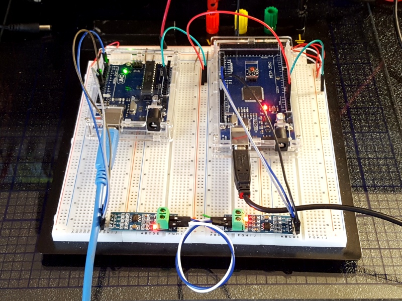
The programs below create both a Master device and a Slave device. For this setup, you will need two Arduinos of any type (or other microcontrollers) and two of the RS-485 modules. You will download the Master software to one device and the Slave software to the second device. The programs use the SoftSerial library for communication in order to leave the hardware serial port available for monitoring the data on the Serial Monitor windows of the two Arduinos. If you are using a version of board that has multiple hardware serial ports, you can use one of those instead if you prefer but it is recommend to get the setup up and running as shown first, then start making mods.
Both devices use the same pins for their soft serial port. Connect as follows from Arduino to RS-485 module on both devices
- Pin 10 (RX) connects to RO
- Pin 11 (TX) connects to DI
- Pin 3 (CTRL) connects to RE and DE.
- 5V connects to VCC
- Gnd connects to Gnd
Connect data lines A to A and B to B between RS-485 modules. You can use either the terminal block or the header pins to make these connections.
The Master device allows you to type any character in the top portion of the Serial Monitor window and once you press enter, it will send that character to the Slave device.
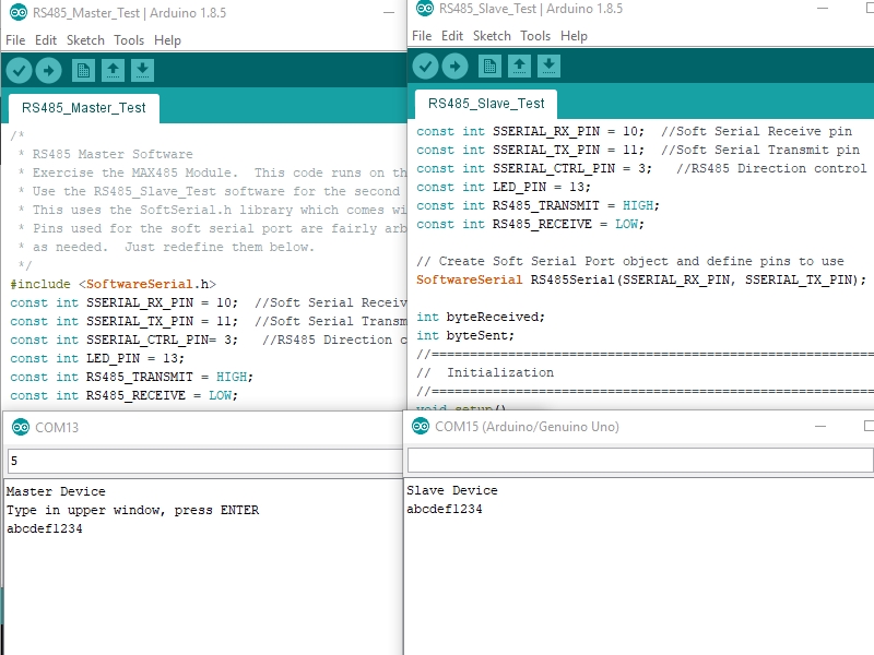
When the Slave receives the character, it will send what it received out to its own Serial Monitor window as well as echo it back to the Master device. Once the Master device receives the character back from the Slave, it will print it out to its own Serial Monitor window. Basically, if you type an ‘a’ and hit ENTER in the top window of the Master device and you see an ‘a’ appear in the bottom window, the command has made a full round trip.
Note that if you want to use the Serial Monitor Window on both the Master and Slave device at the same time, or program both Arduinos without moving USB cables around and resetting COM ports and Arduino types, you will need to create two instances of the Arduino IDE.
To do that, you just need to open the IDE from the Start menu (or where ever you typically open it) twice. You cannot just open a 2nd window from an existing IDE. Once you have two separate IDEs running, open the Master software in one and the Slave software in the 2nd. Configure both for the COM port and the Arduino type you are using with each window. You will of course also need two USB cables to connect both Arduinos up to your PC at the same time.
Master RS-485 Device Software
#include <SoftwareSerial.h>
const int SSERIAL_RX_PIN = 10;  //Soft Serial Receive pin
const int SSERIAL_TX_PIN = 11;  //Soft Serial Transmit pin
const int SSERIAL_CTRL_PIN= 3;   //RS485 Direction control
const int LED_PIN = 13;
const int RS485_TRANSMIT = HIGH;
const int RS485_RECEIVE = LOW;

// Create Soft Serial Port object and define pins to use
SoftwareSerial RS485Serial(SSERIAL_RX_PIN, SSERIAL_TX_PIN); // RX, TX

int byteReceived;
//===============================================================================
//  Initialization
//===============================================================================
void setup()
{
  Serial.begin(9600);           // Start the built-in serial port
  Serial.println("Master Device");
  Serial.println("Type in upper window, press ENTER");

  pinMode(LED_PIN, OUTPUT);     // Configure any output pins
  pinMode(SSERIAL_CTRL_PIN, OUTPUT);

  digitalWrite(SSERIAL_CTRL_PIN, RS485_RECEIVE);  // Put RS485 in receive mode

  RS485Serial.begin(9600);   // Start the RS485 soft serial port
}
//===============================================================================
//  Main
//===============================================================================
void loop()
{
  if (Serial.available())         // A char(byte) has been entered in the Serial Monitor
  {
    byteReceived = Serial.read();                   // Read the byte
    digitalWrite(SSERIAL_CTRL_PIN, RS485_TRANSMIT);  // Put RS485 in Transmit mode
    RS485Serial.write(byteReceived);                 // Send byte to Remote Arduino
    delay(1);                                        // Wait before going back to Receive mode
    digitalWrite(SSERIAL_CTRL_PIN, RS485_RECEIVE);   // Put RS485 back into Receive mode
  }

  if (RS485Serial.available())            //Data from the Slave is available
   {
    digitalWrite(LED_PIN, HIGH);          // Show activity on LED
    byteReceived = RS485Serial.read();    // Read received byte
    Serial.write(byteReceived);           // Show on Serial Monitor
    delay(10);
    digitalWrite(LED_PIN, LOW);           // Turn LED back off
   }
}
Slave RS-485 Device Software
#include <SoftwareSerial.h>

const int SSERIAL_RX_PIN = 10;  //Soft Serial Receive pin
const int SSERIAL_TX_PIN = 11;  //Soft Serial Transmit pin
const int SSERIAL_CTRL_PIN = 3;   //RS485 Direction control
const int LED_PIN = 13;
const int RS485_TRANSMIT = HIGH;
const int RS485_RECEIVE = LOW;

// Create Soft Serial Port object and define pins to use
SoftwareSerial RS485Serial(SSERIAL_RX_PIN, SSERIAL_TX_PIN);

int byteReceived;
int byteSent;
//===============================================================================
//  Initialization
//===============================================================================
void setup()
{
  Serial.begin(9600);         // Start the built-in hardware serial port
  Serial.println("Slave Device");

  pinMode(LED_PIN, OUTPUT);   // Configure any output pins
  pinMode(SSERIAL_CTRL_PIN, OUTPUT);

  digitalWrite(SSERIAL_CTRL_PIN, RS485_RECEIVE);  // Put RS485 in receive mode

  RS485Serial.begin(9600);   // Start the RS485 soft serial port
}
//===============================================================================
//  Main
//===============================================================================
void loop()
{
  // Watch for data coming in on the soft serial port.  If found, send a copy to the
  // hardware port to display on the local serial terminal and also echo a copy back out
  // the soft serial port to the Master device
  if (RS485Serial.available())        // If data has come in from Master
  {
    byteSent = RS485Serial.read();    // Read the byte
    Serial.write(byteSent);           // Show on local Serial Monitor window
    digitalWrite(LED_PIN, HIGH);      // Show activity on LED
    delay(10);

    digitalWrite(SSERIAL_CTRL_PIN, RS485_TRANSMIT);  // Put RS485 in Transmit mode
    RS485Serial.write(byteSent);                     // Send the byte back to Master
    delay(1);                                        // Wait before going back to Receive mode
    digitalWrite(SSERIAL_CTRL_PIN, RS485_RECEIVE);   // Put RS485 back into Receive mode
    digitalWrite(LED_PIN, LOW);                      // Turn LED back off
  }
}
Notes:
- Note that due to the length of the module, if using with a breadboard, you will need to span two sections of the breadboard.
- For a simpler to use and more capable solution with auto direction control, check out the SCM TTL to RS-485 Interface Module below