


Description
A relay is an electromechanical device that uses an electric current to open or close the contacts of a switch. The single-channel relay module is much more than just a plain relay, it comprises of components that make switching and connection easier and act as indicators to show if the module is powered and if the relay is active or not.
Specifications
- Supply voltage – 3.75V to 6V
- Quiescent current: 2mA
- Current when the relay is active: ~70mA
- Relay maximum contact voltage – 250VAC or 30VDC
- Relay maximum current – 10A
Pinout
|
Pin Number |
Pin Name |
Description |
|
1 |
Relay Trigger |
Input to activate the relay |
|
2 |
Ground |
0V reference |
|
3 |
VCC |
Supply input for powering the relay coil |
|
4 |
Normally Open |
Normally open terminal of the relay |
|
5 |
Common |
Common terminal of the relay |
|
6 |
Normally Closed |
Normally closed contact of the relay |
Understanding 5V Single-Channel Relay Module
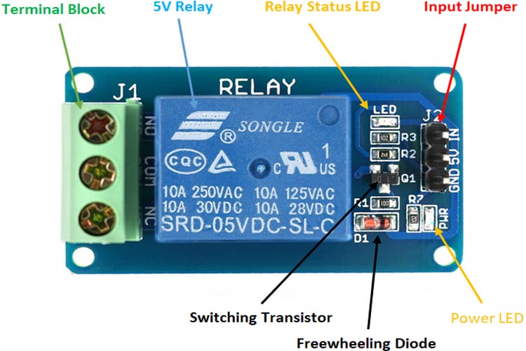
The single-channel relay module is much more than just a plain relay, it contains components that make switching and connection easier and act as indicators to show if the module is powered and if the relay is active.
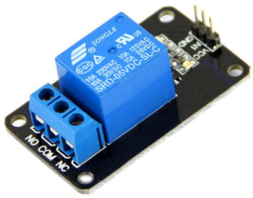
First is the screw terminal block. This is the part of the module that is in contact with mains so a reliable connection is needed. Adding screw terminals makes it easier to connect thick mains cables, which might be difficult to solder directly. The three connections on the terminal block are connected to the normally open, normally closed, and common terminals of the relay.
The second is the relay itself, which, in this case, is a blue plastic case. Lots of information can be gleaned from the markings on the relay itself. The part number of the relay on the bottom says “05VDC”, which means that the relay coil is activated at 5V minimum – any voltage lower than this will not be able to reliably close the contacts of the relay. There are also voltage and current markings, which represent the maximum voltage and current, the relay can switch. For example, the top left marking says “10A 250VAC”, which means the relay can switch a maximum load of 10A when connected to a 250V mains circuit. The bottom left rating says “10A 30VDC”, meaning the relay can switch a maximum current of 10A DC before the contacts get damaged.
The 'relay status LED' turns on whenever the relay is active and provides an indication of current flowing through the relay coil.
The input jumper is used to supply power to the relay coil and LEDs. The jumper also has the input pin, which when pulled high activates the relay.
The switching transistor takes an input that cannot supply enough current to directly drive the relay coil and amplifies it using the supply voltage to drive the relay coil. This way, the input can be driven from a microcontroller or sensor output. The freewheeling diode prevents voltage spikes when the relay is switched off.
The power LED is connected to VCC and turns on whenever the module is powered.
Single-Channel Relay Module Basic Trouble Shooting
If the relay does not switch on, i.e. no audible clicking sound is heard:
- The contacts might be stuck - Check by physically shaking the relay, if a light clicking sound is not heard, then tap the relay hard, in most cases, this should ‘unstick’ both the contacts.
- If the contacts do click when the relay is shaken, then the transistor or the flyback diode might be damaged and must be replaced.
Single-Channel Relay Module Applications
- Mains switching
- High current switching
- Isolated power delivery
- Home automation