


Description
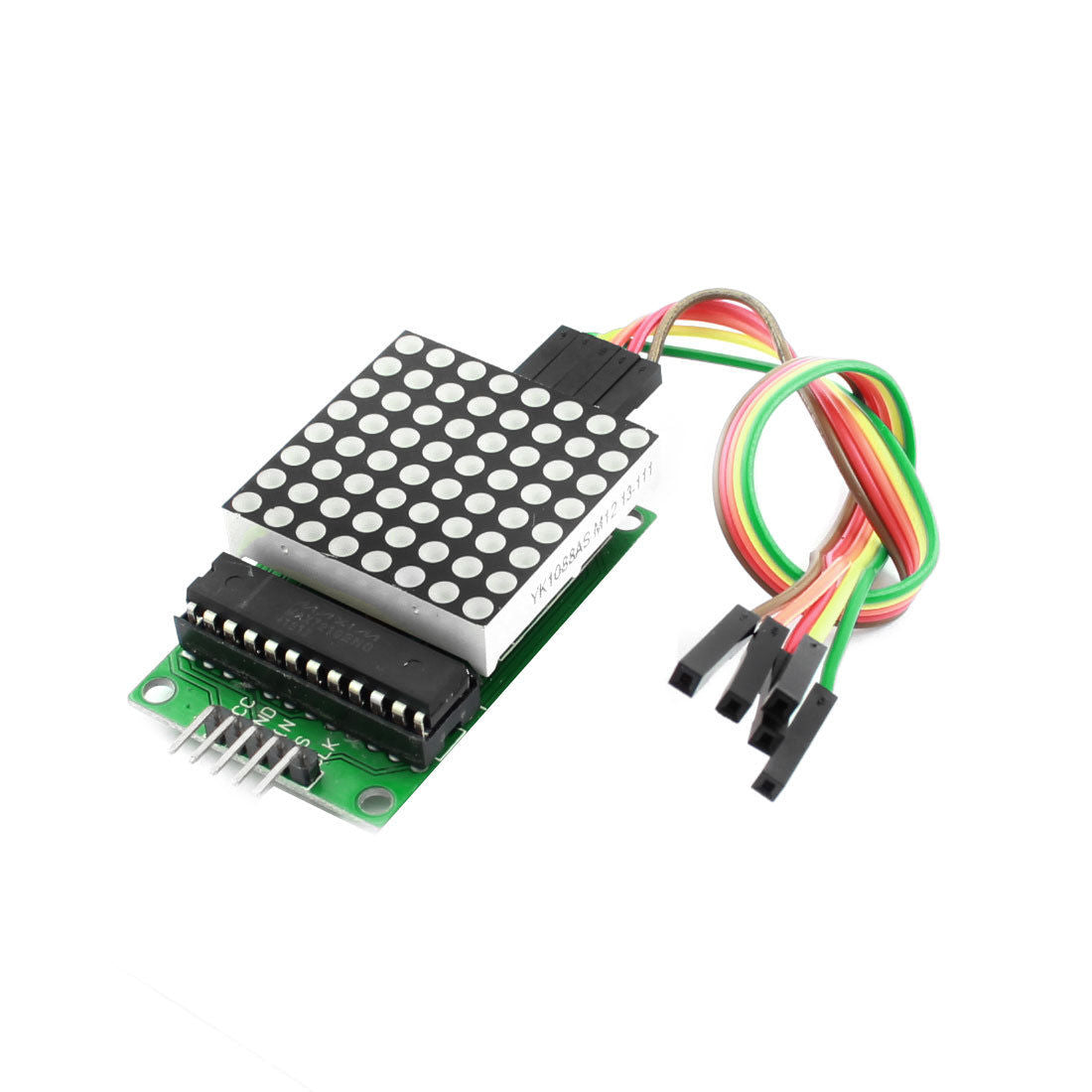
This is Dot Led Matrix Module incorporating MAX7219 Driver chip. By using this dot LED module in your upcoming project, you will be able to add some great cool animation.
The individual module features 8×8 LED’s, each controlled very precisely by the MAX7219 driver to generate the color pattern you wish. The great advantage of using this is users will have control over all of the 64 LED by just connecting 3 output communication wires to microcontrollers like Arduino etc.
Connecting the two modules is also very easy. Only connect the output pins of the previous breakout board to the input pins of the new module, thus with such arrangement, you can connect as many DOT LED Modules to the Arduino as you wish!!! Great……
The MAX7219 Dot Led Matrix Module MCU Control LED Display Module is a serial input common-cathode driver that interfaces micro-controllers to LED matrices. All common micro-controllers can be connected to this module by using a 4-wire serial interface. Each output can be addressed without refreshing the entire display. This module requires only 3 I/O lines for driving the display, making it ideal for your microcontroller projects. Only one external register is used to set the segment current of each LED.
Specifications
| Product Name | Red Dot Matrix Module |
| Model | MAX7219 |
| Working Voltage | DC 5V |
| LED Number | 8 x 8/ 64 |
| LED Light Color | Red |
| Body Size | 50 x 32 x 13mm/2" x 1.2' x 0.5(L*W*T) |
| Cable Length | 20cm/7.8" |
| Mounted Hole Center Distance | 43 x 27mm/1.7" x 1.1"(L*W) |
| Material | Plastic, Electronic Part |
| Board Main Color | Green, Black, and White |
| Cable Color | Yellow, Red, Brown,Orange, Green |
| Net Weight | 21g |
| Package Content | 1 x Red Dot Matrix Module 1 x 5 Pin Cable |
Package Includes
- 8x8 LED MAX7219 DOT Matrix Display Module.
- 5pcs female to female jumper wire.
Pin Connection
Dot LED Module to the Arduino
Vcc – 5V
GND – GND
DIN – Pin 12
CS – Pin 10
CLK – Pin 11
MAX7219 Module Pinout

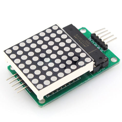
Input Connector
The breakout pins on one end of the module are used to communicate with the microcontroller.
VCC is connected to 5V. Because the display draws a lot of current (up to 1A at maximum brightness), it’s best to use an external power supply instead of the Arduino’s 5V supply. If you want to use the Arduino’s 5V supply, keep the brightness below 25% to avoid overheating the voltage regulator.
GND is the common ground pin.
DIN is the Data pin. Connect it to any digital pin of the microcontroller.
CS/LOAD is Chip Select (sometimes labeled as LOAD). Connect it to any digital pin of the microcontroller.
CLK stands for Clock pin. Connect it to any digital pin of the microcontroller.
Output Connector
The breakout pins on the other end of the module are used to daisy-chain displays.
VCC connects to 5V on the next module.
GND connects to GND on the next module.
DOUT is Data Out and connects to the DIN pin of the next module.
CS/LOAD connects to CS / LOAD on the next module.
CLK connects to CLK on the next module.
Wiring MAX7219 Module with Arduino UNO
Now that we know everything about the module, we can start hooking it up to our Arduino!
Let’s start with the module’s power supply connections. Because the display consumes a lot of current, we’ll use an external power supply instead of the Arduino board’s 5V supply. If you are only using a single MAX7219 module, you can power it directly from the Arduino, but you should avoid doing so if possible.
Let’s wire up the SPI pins. Note that each Arduino board has a unique set of SPI pins that must be connected accordingly. For Arduino boards such as the UNO/Nano V3.0, these pins are digital 13 (SCK), 12 (MISO), 11 (MOSI), and 10 (SS).
If you’re using a different Arduino board, check the official documentation for SPI pin locations before proceeding.
Here is the wiring for the Generic MAX7219 Module:

Library Installation
Controlling the MAX7219 module is a lot of work. Fortunately, the MD Parola library was written to hide the complexities of the MAX7219, allowing us to control the display with simple commands.
To install the library, navigate to Sketch > Include Library > Manage Libraries… Wait for the Library Manager to download the library index and update the list of installed libraries.

Filter your search by entering ‘max72xx’. Look for MD_MAX72XX by MajicDesigns. Click on that entry and then choose Install.

The MD_MAX72XX library is a hardware-specific library that handles lower-level functions. It must be used in conjunction with the MD_Parola Library to create a variety of text animations such as scrolling and sprite text effects. Install this library as well.

Arduino Example Code – Printing Text
Our first experiment involves displaying a simple text without any animation.
But, before you upload the sketch, you must modify the following two variables.

The first variable, HARDWARE_TYPE, informs the Arduino of the module variant.
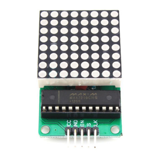
- Set the
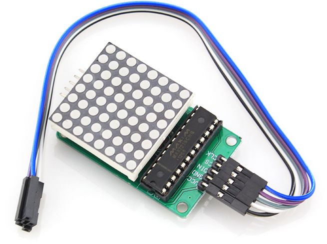
HARDWARE_TYPEtoGENERIC_HW, if you’re using a module with a green PCB and a through hole MAX7219 IC like the one shown below.
- Set the
HARDWARE_TYPEtoFC16_HW, if you’re using a module with a blue PCB and an SMD MAX7219 IC like the one shown below.
The second variable, MAX_DEVICES, specifies the number of MAX7219 ICs being used. A single MAX7219 IC counts as one device, so if you want to control an 8×32 display, set MAX_DEVICES to 4 because an 8×32 display has four MAX7219 ICs.
When you’re finished, try out the sketch, and then we’ll go over it in detail.
// Including the required Arduino libraries
#include <MD_Parola.h>
#include <MD_MAX72xx.h>
#include <SPI.h>

// Uncomment according to your hardware type
#define HARDWARE_TYPE MD_MAX72XX::FC16_HW
//#define HARDWARE_TYPE MD_MAX72XX::GENERIC_HW

// Defining size, and output pins
#define MAX_DEVICES 4
#define CS_PIN 3

// Create a new instance of the MD_Parola class with hardware SPI connection
MD_Parola myDisplay = MD_Parola(HARDWARE_TYPE, CS_PIN, MAX_DEVICES);

void setup() {
	// Intialize the object
	myDisplay.begin();

	// Set the intensity (brightness) of the display (0-15)
	myDisplay.setIntensity(0);

	// Clear the display
	myDisplay.displayClear();
}

void loop() {
	myDisplay.setTextAlignment(PA_LEFT);
	myDisplay.print("Left");
	delay(2000);

	myDisplay.setTextAlignment(PA_CENTER);
	myDisplay.print("Center");
	delay(2000);

	myDisplay.setTextAlignment(PA_RIGHT);
	myDisplay.print("Right");
	delay(2000);

	myDisplay.setTextAlignment(PA_CENTER);
	myDisplay.setInvert(true);
	myDisplay.print("Invert");
	delay(2000);

	myDisplay.setInvert(false);
	myDisplay.print(1234);
	delay(2000);
}
Output
To see the output, the display must be properly oriented. If you’re using a generic module, make sure the MAX7219 IC is on top. If you’re using an FC-16 module, make sure the DIN side is on the right side.
If everything goes well, you will see the following output.

Code Explanation
The first step is to include all the necessary Arduino libraries. As previously stated, the MD_MAX72XX library implements the hardware-specific functions of the LED matrix, whereas the MD_Parola library implements the text effect. You must also include the SPI library, which is used to communicate with the display via SPI.
#include <MD_Parola.h>
#include <MD_MAX72xx.h>
#include <SPI.h>
Next, we must specify which hardware is being used. Because we are using an FC-16 module for our experiments, the HARDWARE_TYPE is set to FC16_HW. We’re using 4 MAX7219 ICs, so MAX_DEVICES is set to 4. Finally, the pin to which the display’s CS pin is connected is defined.
#define HARDWARE_TYPE MD_MAX72XX::FC16_HW
#define MAX_DEVICES 4
#define CS_PIN 3
The function MD_Parola() is then used to create a new instance of the MD_Parola class. The first parameter is the hardware type, the second is the CS pin, and the third is the number of MAX7219 ICs being used.
MD_Parola myDisplay = MD_Parola(HARDWARE_TYPE, CS_PIN, MAX_DEVICES);In the setup section of the code, we first use the function begin() to initialize the object. The brightness of the display can be adjusted using the function setIntensity(), which accepts values ranging from 0 (lowest brightness) to 15 (maximum brightness). The display is cleared using the displayClear() function.
void setup() {
  myDisplay.begin();
  myDisplay.setIntensity(0);
  myDisplay.displayClear();
}
In the loop section of the code, we first set the alignment of the text to be printed with the function setTextAlignment(), to which the values PA_LEFT, PA_CENTER, and PA_RIGHT can be passed to align the text to the left, center, or right, respectively.
The string ‘Left’ is then printed using myDisplay.print("Left"). Please keep in mind that the text string should be enclosed in quotation marks " ". When printing numbers, no quotation marks are required; for example, to display 1234, write myDisplay.print(1234). You can also use the setInvert() function to invert the display.
void loop() {
	myDisplay.setTextAlignment(PA_LEFT);
	myDisplay.print("Left");
	delay(2000);

	myDisplay.setTextAlignment(PA_CENTER);
	myDisplay.print("Center");
	delay(2000);

	myDisplay.setTextAlignment(PA_RIGHT);
	myDisplay.print("Right");
	delay(2000);

	myDisplay.setTextAlignment(PA_CENTER);
	myDisplay.setInvert(true);
	myDisplay.print("Invert");
	delay(2000);

	myDisplay.setInvert(false);
	myDisplay.print(1234);
	delay(2000);
}